|
Introduction
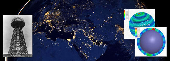
Few years ago, the authors of this article, were thoroughly examining patents, notes and lectures of Nikola Tesla (thanks to our education). Eventually, we came to conclusion that notorious wireless energy transmission Tesla Tower is not "fake".
In fact, it
is quite useful construction.
Elaborated concept was tested and conformed by means of computational modeling approach using software package called as Ansoft HFSS.
Once the project began, we have
initiated some discussions in different communities, where we were
expected to have some sort of scientific article. This was the main
reason for preparation of this material.
Hence, please kindly
familiarize yourself with this content in order to gain better
understanding of proposed concept and to be able to take part in
constructive discussion afterwards.
The initial stage of our research comprised thorough examination of the working principle of the Tesla Tower taking into consideration all the notes and patents provided by its principal developer.
As a result, deeper understanding of physical processes given a rise to in the planet of Earth was gained. Therefore, it became clear to us that it is possible to perform power transmission by means of proposed and tested Tesla's approach. At that, we relied upon the fact that Tesla's patent is very descriptive on its nature and there are no any "hidden" parameters/processes existing.
That is why we assume that so-called "ideas", which are actively discussed in tabloids and mass media concerning the suggestion that Tesla undertook an attempt to "get environmental power" and use "radiant energy" via his power etc., are purely journalists' speculations that are very far from real physics.
In our opinion, working principle of the Tesla Tower completely corroborates with conventional physics laws and does not require complementary use of any other new concepts or physic effects. Therefore, our research and future investigation has solely applicative and by no means fundamental nature.
If the nature of our article seems to be too
complex for you, please kindly take a look at the
article located here
(this one is rather written for humanists and contains a series of
rather incorrectly formulated concepts, however this source would
help you to gain better understanding of the concept).
Tesla Tower - features of working principle
In principle, without considering specific technical peculiarities, Tesla Tower is helically formed quarter-wave resonator grounded by one tail with distributed parameters, and additional capacity being located in the upper end of the helix.
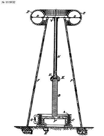
This resonator is oscillated
by means of reference generator (sinusoidal signal, oscillation
frequency value is lower than 20 kHz if based on Tesla's patents
such as US787412 and US1119732).
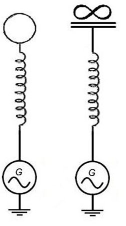
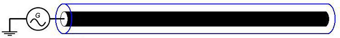
On the left, you can see physical isolated capacity located in the top of tower (complements own coil's capacity).
On the right, you can observe conditional equivalent circuit, where it is especially outlined that the capacity is isolated. According to that drawing, capacity is located between Tower and perpetuity and not between Tower and the Earth as otherwise we would get conventional LC-chain grounded through the Earth).
For the purpose of minimization of stray capacity between the Tower and the Earth, that is, shortcutting LC-chain of the Tower through the Earth, it is necessary to elevate isolated capacity from the ground. Simple assessment demonstrated that it is needed to elevate the capacity to the height, which is equal on its value to several average diameters of such capacity.
At the observation of such condition, capacity
between the Tower and the Earth will decrease on its value up to the
value, which is comparable with own isolated capacity of the Tower.
Therefore, generator "observes" only active resistance of the resonator. Standing wave with the voltage node in the generator point occurs in the helix. Current loop is located there, as well (at that, voltage loop and current node are located in the resonator's tail).
More detailed analytical theory of the working principle of such resonator can be found here.
If material located there is too complex to be understood, it is possible to express everything said above in the following way: helically formed resonator of such kind simply represents quarter-wavelength transmission line folded up into helix. That is, standing wave of the current-voltages will exist in such "stretched" transmission line in such resonator at the resonant frequency with the voltage node at the one end of a line and current node on its other end.
Essential different of that from the "stretched" long transmission line is only in amplified inductive and capacitive connection between neighboring segments of such a line due to the their geometrical proximity in helical configuration.
The latter slightly alters resonant frequency and wave propagation speed along the line.
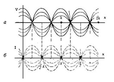
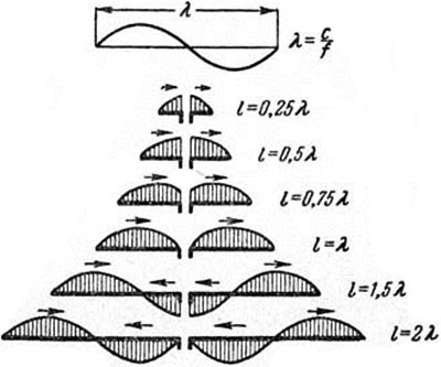
In this Figure, you can see standing waves in long transmissionline. Waves' distribution is as follows: а - of the voltage; b - that of the current in single-wired transmission line
(figure is taken from the following
website)
At that, the greatest part of the currents
(current loop) is concentrated in the lower half of the Tower.
Hence, such a structure acts as classical conventional
concentrated inductivity in terms of external EM-radiation. It
is conventional magnetic dipole.
(equation 8.148 can be found by checking the
link indicated above)
Using our parameters such as frequency with the value of 10 kHz,i.e. wavelength of 30 000 m, coil radius being about 2 m, winding length being of 10km, and number of the turns being of 800, we will get the radiation resistance with the value of 0.04 micro ohms.
The latter is insignificantly small in comparison to the losses on the active resistance of a system, which comprises at least 1 ohm.
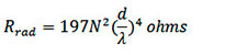
However, except of tangential constituent of the current in such resonator, there is also axial component (resulting vertical current) because of which the Tower provides radiation of the short electrical dipole for which the radiation resistance is interrelated with the length of dipole denoted as L and wavelength denoted as λ as follows:
So any kind of ideas of the Tower operating as an antenna is absurd (at least, while we adhere the Tesla's patents and do not exhibit any personal speculations).
The Tower cannot be considered as antenna in its classical understanding. Its radiation, that is, EM-field in the distant wave zone is insignificantly small and the tower can serve only as effective accumulator for charge, which is being brought in and out the ground by the generator at its working frequency.
Therefore, "genial" objections like "you will get conventional
helical antenna with very low power transmission efficiency value"
as well as any other "objections" based on radiation of such a
structure only demonstrate total misunderstanding of the basic
principles of radio physics by the opponent.
Now let us proceed with the Earth
To make it simple, let us start from simple analogies and then proceed with the final concept.
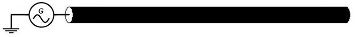
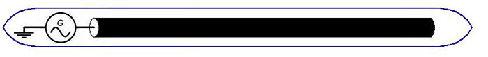
Let us assume that we have electrically long conductor with the break in one tail and grounded by the other tail through the ac voltage source (and by electrically long we mean that the length of the conductor is comparable to/greater than that of the wave initiated by the generator based on the generator's frequency and wave propagation velocity being close to the light speed in vacuum):
In such long transmission line and in a case when losses within the line are very small, standing wave of the currents and voltages occurs (i.e. superposition of the incident waves from the generator and the waves reflected from the free end of the long line).
Conventional electrical vibrator or classical antenna can be considered as a typical example of such lines and waves as shown in the Figure below.
Current
distribution in symmetrical vibrating-reed relays of different
length
Let us assume that conductor is divided into the segments with the length being half-size of that of the wave. Each of such segments is considered as a capacity (as conductor has a capacity distributed along) and as an inductivity (in an analogous manner). Hence, standing waves are nothing else but current waves charging/discharging such the capacities.
That is, energy in such standing wave is saved as a charge and current in an interchangeable manner. Such a charge is either allocated along the conductor (along the sine wave) with the current values being equal to zero or in the form of the currents redistributed along the conductor (along the sine wave, correspondingly).
At this moment, surface charge density along the conductor is equal to zero. The latter just resembles the working pattern of conventional LC-chain (induced coil sequentially connected with the condenser capacity) but with regard to distributed manner of capacity and inductivity. The currents in half-wave are "drawn" to the center of such selected segment creating voltage loop i.e. occurrence of surface charge in the conductor.
As of the neighboring segment, such currents are "drawn away" from similar center creating a charge of opposite sign.
This process is repeated further to the opposite side whilst creating the charges of opposite sign at the surface of a conductor. It is obvious that all aforesaid implies ideal transmission line without losses and being open-ended at the tail. More complex processes are happening in real transmission line with the losses and/or line with the load at the tail.
However, it does not affect
principal essence of the subject in question.
At that, movement velocity of the respective part of a spring corresponds to the current value, and an extent of spring compression depends on the voltage value. Thus, all parts of a spring will acquire zero velocity at some point while extent of spring compression will vary on sine and along spring so it may resemble some kind of alternative nodes and discharges.
The latter is determined by zero current in standing wave and maximum voltage value simultaneously (i.e. maximum value of surface charge density in the conductor).
It is also possible that whole spring will not be deformed over quarter of period of time, however actual velocity of its parts will vary on sinus along axis of a spring at the moment (the moment of zero charge density but with a maximum current value along the long line conductor correspond to that).
In general, losses in such transmission line can be divided in two constituents: ohmic losses and losses by radiation.
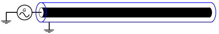
Such structure is called as coaxial waveguide. It is noteworthy that in our example, wave in such coaxial waveguide will exist in a form of ТЕМ-mode (generator connected via ground to the internal and external conductors of a waveguide will serve as an excitation port).
Actually, state of ТЕМ mode can be considered as a state of inductive connection of internal and external conductors of waveguide via induction field in these conductors (current change in the internal core evokes EMF in the external screen. At that, induced current in the external screen directed against the current change in the internal core, i.e. it is actually conventional induction in the near field of a current).
Therefore, cross flows of energy are not only of a zero value for both ТЕ and ТМ mode over time in average, but they are also of a zero value at any moment of time. Re-reflection from the boundaries of waveguide does not take place.
In this case, energy flow has dilatational nature, that is, directed along the axis, and correspondingly Poynting's vector is directed also in strictly parallel direction of wave propagation along the axis of such coaxial resonator.
This is due the fact that such screen represents transmission line anyway, where EMF of alternating current in internal conductor-core is used as a generator.
And some kind of voltage loop
will exist only in the end parts of such screen due to small value
of capacity of these ends. The rest part of screen will be fully
functional. The latter can be proven by means of elementary modeling
in Ansoft HFSS software for example.
Screen
will operate on its entire length but the endings of such "capsule"
will gather voltage loops as well as current nodes.
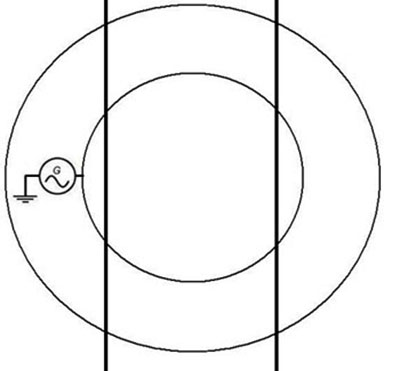
Even if internal and
external conductors can be designed as the spheres, we will end up
with the general model of suggested experiment (proportions in
Figure below were not adhered):
It is easy to guess that internal conductive sphere is the Earth while upper layers of atmosphere (mainly ionosphere) represent internal conductive sphere.
And general geometry of such resonator
is just conventional concentric spherical resonator in which only
ТЕ
and
ТМ
mode exist so we can't talk only of TEM mode. However, such
resonator has quite unconventional way of excitation of the
ТМ-mode
(that is, excitation port does not connect external and internal
plates like it is accomplished in "classical" electrical
engineering).
We assume that from the viewpoint of current flow processes, division to dielectrics, semiconductors and conductors is quite conditional on its nature as dielectric becomes comparably good conductor at its great section (that is, dielectric has small total resistance value while has small conductivity also).
...where,
Obviously, this is a simplified equation, which can be used for the conductor but not for dielectric. However, the losses related to permittivity of the grounds are very small at our ultra low frequencies.
Therefore, this equation can be used for performing an
assessment.
Let us notice
that obviously Tesla sincerely assumed that currents from his tower
are directed inside of the Earth and not to its surface as it is
indicated in our scientific article. According conventional
electrodynamics, this is wrong assumption.
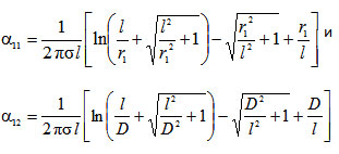
Where,
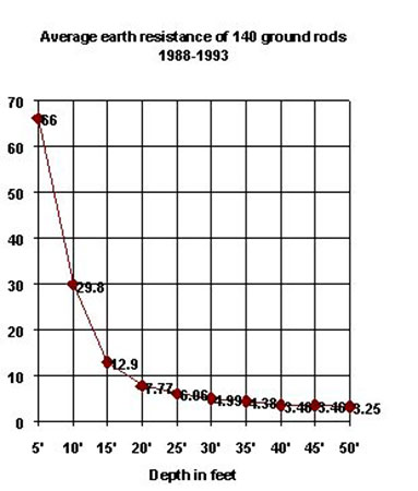
It is noteworthy that based on this equation and starting from the distance between the bars, which exceeds the length of the bars, resistance between bars actually becomes constant (stops to increase as the distance grows).
Thus, it is intuitive delusion
that the Earth is bad conductor (as an object in general). In
opposite case grounding wouldn't make any sense - while it is used
everywhere.
The latter is well-known fact in terms of grounding systems:
Thus, we have to be optimistic in relation to resistance of entire surface of the Earth.
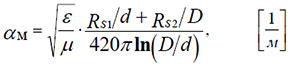
Let us perform an assessment in a more precise manner. Attenuation constant defining losses on the walls of the waveguide due to active resistance for ТЕМ-mode of coaxial waveguide
(to which the biggest central part of the Earth-resonator is most
closely located as shown in Figure above) is calculated according to
the following equation (see for
example here
or
here
- eq. 10.4.8):
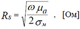
...where Rs1 and Rs2 are surface resistances of metal of internal and external cylinders of the waveguide, which can be calculated according to the following equation:
Here µ is
permeability
(for the most parts of superficial ground it is just
magnetic constant).
The fact of their ratio being located under root sign "improves" situation even more.
Thus, we receive variable
with the value of 1.06 ohm for our parameters such as f=3 kHz and
σ=0.01
Cm/m which is typical value of surface resistance of both The Earth
and ionosphere with the 1ohm-period±period.
In our case, radiuses D and d have great value (D=6.600.000 m, d = 6.400.000 m), which completely exceeds relatively great value of surface conductivity of the walls of the waveguide.
Therefore, attenuation constant for our parameters
can be assessed using the equations indicated above as having value
of 10-8-10-9 1/m.
However, speaking of frequencies with the value range being within few kHz, except of zero mode the following ones will be subjected to excitation (for 10 кHz these are mode numbers within range of 0-6).
Hence, as it can be seen from equation,
...for the first mode - the lowest harmonic will have frequency with the value of about 1.5 kHz, and for the second mode this value will be 3 kHz etc.
At that, as it can be seen from the equation defining harmonic frequencies for each of such modes starting from the first one and so forth, "density" of harmonics location along frequency axis is quite big (for instance, if harmonics come with an interval of about 10Hz for zero mode then for the rest of modes within frequency range being below 10kHz this value will be with an interval of about 0.01-0.1Hz).
Therefore, it is impossible to talk about any concrete mode/harmonic while performing excitation of ТМ-modes of such resonator at the frequency range being of few kHz: final situation with standing waves will correspond to exceedingly large amount of harmonics for several modes at once.
The latter serves as
a principal difference of such resonance from Shuman's one.
However, resonator Earth-Ionosphere is not passive on its nature. In reality, electrical machine of the Earth keeps approximately constant voltage difference between the plates of planetary condenser (ground-atmosphere). In case of strike of lighting, given voltage decreases, however its value returns to normal during definite period of time measured in seconds.
At that, typical charging current density comprises about 0.1-1A per square kilometer. In other words, the Earth operates as EDS source, which slowly stabilizes voltage difference at some kind of average level. Obviously in case of ultra-low frequency oscillations corresponding to the Shuman's resonance (first harmonics of zero ТМ-mode of resonator), presence of such EDS source results in significant worsening of Q-factor of resonance.
In case of voltage potential fluctuation from average level, this EDS source aims at compensating of the fluctuation.
The latter implies active suppression of ТМ-mode which can have significant effect taking into consideration planetary scale of this phenomenon. Unfortunately, this factor is not considered in any of known models of TM-mode resonance in Earth-Ionosphere resonator.
The reasons for that are quite understandable - there is no any definite model of mechanism of occurrence of such EDS source as well as this mechanism is significantly non-linear in terms of any kind of phenomenon related to atmospheric electricity. Therefore, any kind of adequate modeling (consideration) of such factor for ТМ-modes of resonator is not possible due to lack of the data.
Nevertheless, the
data are known concerning
Q-factor of the first harmonics of zeroТМ-mode
of the resonator Earth-ionosphere (these data were collected in
2011):
As it can be seen from this table, actual Q-factor value increases quickly with the subsequent increase of a number of the harmonics compared to the radical from the frequency value (i.e. it increases faster than for passive resonator).
This mechanism is going to have
the greatest influence taking into consideration relative "slowness"
of charging mechanism of planetary condenser exactly for the lowest
zero mode harmonics due to the fact that Q-factor value of resonance
will increase with quite great speed along with subsequent increase
of the frequency value.
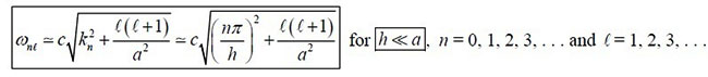
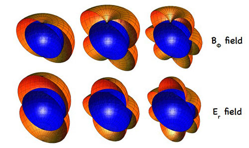
The latter can be confirmed by computational calculations performed by means of Ansoft HFSS software and using corresponding analytical equations like, for instance, for zeroТМ-mode of such resonator:
Distribution of the amplitudes of electrical field E and magnetic field B for the first 3 harmonics of zero ТМ-mode of resonator Earth-Ionosphere, the Figure was taken from here.
As is known in theoretical physics, there is so-called Sommerfeld integral, defining the distribution of EM-field over the surface of the medium with finite conductivity (in the case of an arbitrary location of the radiation source on the boundary between two media).
We could try to use this expression to create the analytic theory of how Tesla Tower works. Indeed, the tower itself can be seen as a set of EM-sources distributed along the height of the Tower, and then using the Sommerfeld integral, we may try directly derive an analytical expression for the wave of current-voltage induced in the ground by the Tesla Tower.
Alas, although itself Sommerfeld integral has been known about 100 years, for all these 100 years, despite the efforts of prominent theorists in the field of physics and mathematics, no one was able to find an analytical solution for the Sommerfeld integral.
It would be naive to believe that we are able to solve this theoretical problem which was not solved by the best minds of the world over 100 years... Thus, all that remains for us - is to be satisfied with the numerical calculation only, which we did - using Ansoft HFSS (as discussed below).
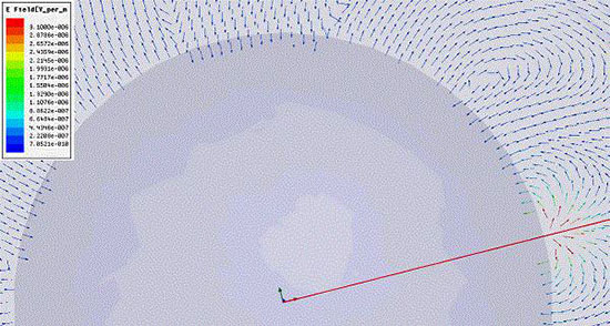
It is noticeable that accordingly Sommerfeld integral, a so-called surface wave (or ground wave) may be generated in case of dipole source placed on the boundary between ground and air. In general Tesla tower is similar to that source. So accordingly Maxwell equations surface wave has to exist at least at short distance (several wavelengths) near the tower.
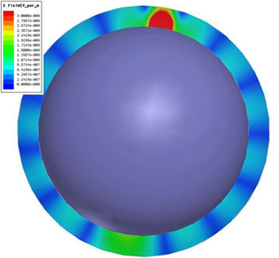
Numerical calculation on HFSS software do confirms that such surface wave can be easily generated by Tesla tower as it is shown at the picture below (Earth is placed in infinite space and has no atmosphere in this calculation - so there is no reflection from ionosphere, nevertheless surface wave still exists; Tower is placed near the right bottom corner).
"Grounding" for the resonator Earth-Ionosphere
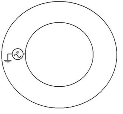
The question is where from we are going to get "grounding" to which generator for pumping such resonator is connected as it is shown in the figure below?
The answer is simple as we have already examined working principle of the Tesla Tower.
From the viewpoint of generator, Tesla Tower is not any different from some kind of external ground (connected via active resistance of the Tower). This is due to the fact that generator "sees" only active resistance of the Tower but does not react anyhow at the charge value, which is accumulated in the tower.
This is because of capacitive and inductive resistance in the
resonance mode compensate each other. In other words, for generator
the Tower is some sort of "grounding" via resistance which is equal
to active resistance of the Tower.
It is enough to elevate charge integrator to the height
which is significantly higher that the size of integrator so that
the Tesla Tower would really start to serve as "external ground" for
the reference generator (i.e. it is enough to minimize the capacity
between the Tower and Earth so that own isolated capacity value of
the Tower would become at least somewhat equal to that of the
capacity Tower-Earth).
Energy transmission efficiency coefficient
Upon establishment of the standing waves of the voltages and currents over all the planet (at that, currents will have quite small amplitude in comparison to the voltages) it is possible to conduct efficient removal of this energy by the analogous system (the same Tower but without generator).
Physical process taking place during the work of a receiver are characterized by the establishment of the connection between Tower-Receiver resonance circuit. The latter allows obtaining quite high transmission efficiency coefficient even at the low coupling coefficient of the source and receiver strictly in correspondence with conventional electrical engineering.
Let us proceed with analysis of this issue in more detailed manner.
In a case of receiver, i.e. similar circuit being located in voltage loop and the current node of the final standing wave, alternating potential of the surface will serve as EDS for receiver. At that, there will happen resonance excitation in the receiver in completely similar manner as that in the source.
Correspondingly, receiver will generate ground wave in a manner similar to that of the source. In addition, as receiver is located in voltage loop and the current node, the generated wave will create additional load to the source and, thus, form the system in a shape of so-called resonance coupled circuits (quick review on this question can be found here and here).
In fact, receiver has voltage node in voltage and current loops of external wave as well as operated at the same frequency, that is, in a field of location of the source where the receiver will create voltage loop and current node and which the source will "see" as additional load.
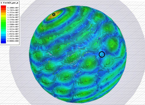
It can be very well observed in the video, which illustrated basics of computational modeling by means of Ansoft HFSS software.
The source is located in the left upper field in the video and in the Figure above, location field of the receiver is selected in the right near-to-central part.
It can be seen that the minimum value of a field in a field of the receiver is constant. The latter indicated efficient removal of the energy from the planetary resonance. Interference image of the waves emitted by the receiver and source is also very clearly visible.
For such kind of systems, that is, resonant coupled circuits, energy transmission efficiency coefficient is determined by multiplication of system coupling coefficient k and its Q-factor. Coupling coefficient defines what part of energy of circuit-source resonance is "seen" by the circuit-receiver.
For instance, coupling coefficient is reaching 1 for the closely located inductive coils (especially if they are spooled on same iron) and subsequently decreases as coils get separated due to the EDC decrease.
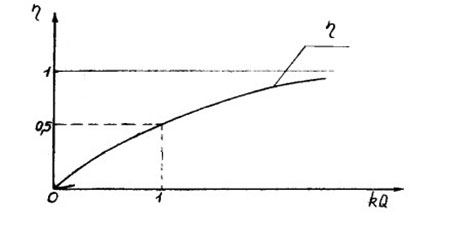
Typical graph of efficiency factor's dependency η from intersection of the coupling coefficient k to Q-factor is provided below:
Physical meaning of such dependency is obvious - even in case when receiver "takes" only small percent of source energy during one oscillation period, energy transmission efficiency factor determining relation of transmitted and dissipated energies will have great value due to the energy losses being small in total resonance during same period of time because of high Q-factor of resonance.
That is, high circuit coupling coefficient is not required for achieving high energy transmission efficiency coefficient value. This is because Q-factor with great value can compensate small value of the coupling coefficient.
Let us assess coupling coefficient between source and receiver and, supposedly, Q-factor of resonator Earth-ionosphere with high value (we have all needed grounds for this assumption based on the facts discussed above).
Let the frequency have a value of 10kHz. It means that the Earth is divided to "rings" with the width being of 30km from which around 700 is accounted for the length of half of perimeter. The capacity of the Earth as isolated conductor has a value of about 700 μF.
Let the current in the Tower (source) have a value of 1kA, which corresponds to the power of generator being at least few MW.
As of the long transmission line - the Earth, our "rings" serve as parallel capacities. That is, capacity per one wavelength within the "Equator" next to the Tower can have a value of 1 μF (700μF/700 waves). The latter provides the voltage with the value of 15kV according to the standard equation such as: U=I*Rc=I/(c1*w) and at the current value being of 1kA (directed for charging of such capacities.
Entire field for TM-mode is concentrated on the length which is equal to the half of wave that is vertical to the ground as it can be seen from computational modeling performed by means of HFSS (and/or corresponding analytical equations links to which were provided above).
For 10 kHz it is 15km.
Field gradient has a value of only one volt pet meter (at the background gradient of vertical constituent of the field being around 100 volts per meter).
Such value is maintained in the "Equator" and what comes to the loops located closely to the Tower the capacity value will be by 1 or even 2 times greater. That is, the Tower-receiver will "notice" voltage value of 100kV (and in such case field gradient will have value of 10V/m) in case when located at the distance of dozens of kilometers from the source.
In this situation, alternating potential of the ground has very big value and field gradient value is so small due to field being distributed vertically along the great distance of dozens of kilometers. The latter allows speaking of even greater power values of a receiver in order do not get away from the gradient level of field located next to the Earth.
In case of the "Equator" and at indicated parameters and total resonance voltage in source having MV value and in the equator having that of 10kV, coupling coefficient will be of 1%, correspondingly (and dozens of % at the distance of dozens of kilometers from source).
This is because of coupling coefficient can be defined as ratio of voltages at the receiver's inductivity at opened circuit of a receiver to the working source given the same parameters of receiver and source. Based on probable Q-factor of resonance being with the value of few hundreds, such coupling coefficient implies energy transmission efficiency ratio being with the value of at least dozens of % for the equator and even can be with a value of above 90% for the distance accounting dozens of kilometers.
The latter completely corroborates with the statements made by Tesla after conduction of corresponding experiments.
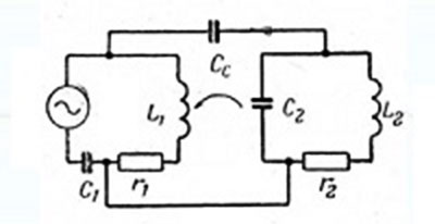
So, in general, it is possible to expect that two Tesla towers (transmitter and receiver) forms capacitive coupled resonant circuits, with capacitive coupling caused by surface waves (in case of short distance between towers, up to several hundreds of kilometers) or waves in Earth-Ionosphere waveguide (for long distance between towers) generated by both towers.
Lumped-circuit scheme of resonant coupling of Tesla Tower (transmitter and receiver).
However, due to problematic issues related to computational modeling and calculations of actual Q-factor of resonance it is not reasonable to attempt to make more precise evaluation (actually all depends on actual Q-factor of the resonator-Earth and resonator-Tower since modeling can result in significant errors).
So the only adequate way of conducting assessment would be elaboration and carrying out full scale experiment. Obviously, for that purpose it is necessary to design full analogue of the Tesla tower.
The latter will allow real representation of the actual "Tesla Tower" and conduction of actual "correct experiment" and subsequent clarification of issue concerning energy transmission efficiency coefficient in terms of energy transmission over the long distances.
At the same time, we have no doubts that the energy transmission efficiency coefficient will have a great value for experimental setup similar to original parameters (taking place in the Tesla's experiments, i.e. in terms of distances ranging at least within hundreds of kilometers).
The latter is interesting from practical viewpoint in any case.
Additional considerations
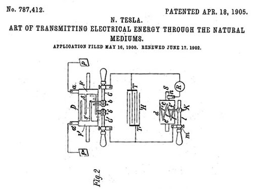
In addition to the patents related to the Tower, Tesla also patented device for location of standing waves of voltages in the ground occurring as a result of lighting strike.
This device is described in patent US787412. The main working principle of given detector is based on ensuring the operating process of so-called synchronous detector or lock-in amplifier).
Some Wikipedia statements are provided below (and are wrong):
It is obvious that Tesla's fellows did not sufficiently research other Tesla's ideas and patents on which he objectively had priorities.
However, more thorough analysis of device detecting standing waves and used by Tesla does not leave any doubts in the fact that invention of synchronous detector has been done by Tesla around 1900 year (not by Robert H. Dicke several dozens of years later).
In fact, Tesla used such device for the purpose of sequential closure of one of the contact of condenser-accumulator with the ground while other contact was "in the air" at the given frequency and pulse ratio (see patent) by means of purely mechanical approach using sliding contacts in corresponding cylinder denoted as F in the Figure below.
Thus, given the condition of closing frequency coalescence of standing wave in the ground and closing frequency of contacts in receiver, condenser Т was gradually accumulating the charge and then involuntary was discharged via receiver R allowing registration of discharging current of such accumulating condenser.
The latter reflects typical logics of lock-in amplifier. At that, as the length of cables connecting condenser with ground was much smaller than wavelength it is not wise to talk of EM-crosstalks for such cables (from lighting strikes) - they are going to be too small.
Here is something Tesla was writing about this and that is where from his path took a start in this field:
Based upon actual detector's design there are no any doubts in the following fact that evidence of operating process of such detector, and in particular, periodical sinusoidal change of amplitude of energetic of the process itself along progress and recession of storm to the hundreds of miles and being registered by the detector definitely implied the fact of presence of standing voltage waves in the ground of Earth.
The latter induced Tesla to commencing of his research.
Based on all information provided above we can assume that there are all necessary grounds for conduction of full scale experiment for the purpose of final confirmation of the important use of the Tesla Tower.
|