|
Colorado Springs
Aug. 12, 1899
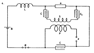
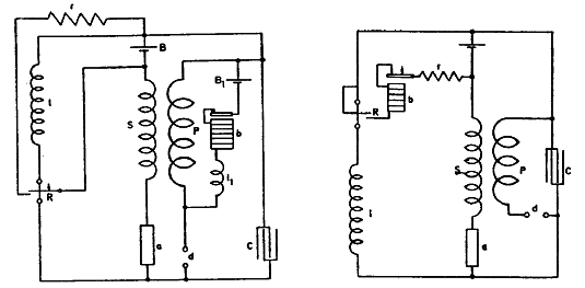
Further modifications in signalling apparatus.
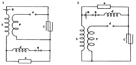
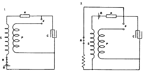
Figs. 1. and 2. show ways of securing initial excitation by means of
very high inductance £ connected as shown.
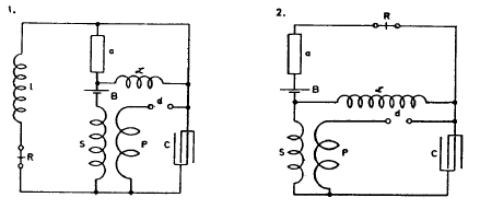
Diagrams 3. and 4. illustrate similar plans of connection. In the
former the battery B is in the main circuit, in the latter in a
shunt to device a.
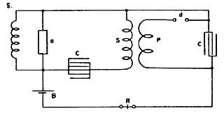
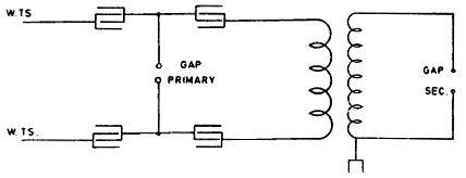
In Figs. 5. and 6. other modified connections are shown. In 5. an
auxiliary secondary S1 with battery and relay is connected around
device a which is excited by main secondary S.
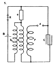
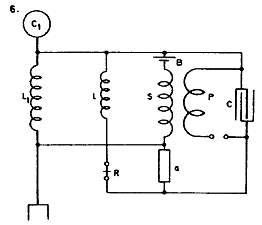
In 6. a similar
connection is used with a buzzer b to excite device a through
secondary S.
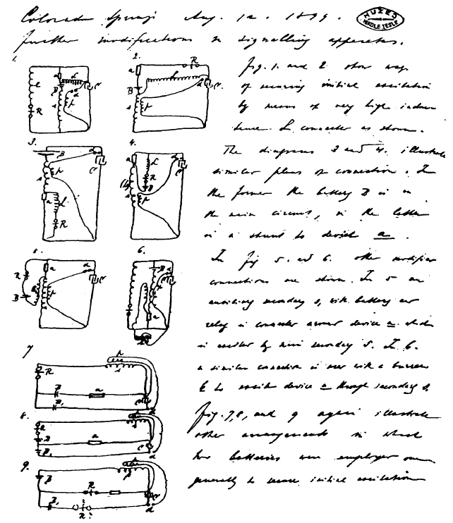
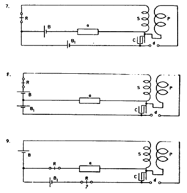
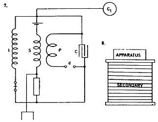
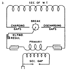
Figs. 7., 8. and 9. again illustrate other arrangements in which two
batteries were employed, one generally to secure initial excitation.
Colorado Springs
Aug. 13, 1899
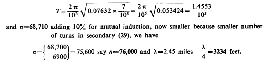
Experiments with oscillator 35—35 1/2 turns. Tension on Westinghouse
Transformer 15,000—22,500 volts. Supply transformers connected 100
volts. 1 primary turn, all jars tension 15,000 volts, effects would
indicate capacity too small.
To ascertain this the connection was changed to 2 primary turns in
series and 1/4 capacity (2 tanks). The capacity was now varied but
resonance effects moderate. All experiments show clearly too much
capacity and comparatively little self-induction in secondary. There
is a large movement in the wire, but pressure can not appear on end
as it would in the absence of capacity.
By adding capacity on one end better results indicate that this view
is true.
One of the balls 38 cm. on end results much better, sparks on
arresters much stronger.
Two balls connected — effects still stronger, sparks livelier on
arresters but the tension still too small. Needs much more capacity
on the end to overcome internal capacity distributed along cable.
Now again changed to one turn as oscillation much better. The extra
coil was added and adjustment of capacity made. Best results with 3
2/3 tanks capacity on each side. An empty tank placed on top of the
coil for capacity. The effects with 22,500 volts on
W.T. remarkable. The streamers very rich red, quickly darting up to
9 feet long. Many brilliant sparks would jump up to a 10 foot
distance.
Colorado Springs
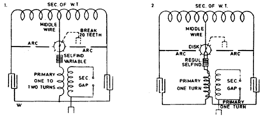
Aug. 14, 1899
The following arrangements with two sensitive devices were the
subject of consideration and experiment today:
This disposition (1.) though it worked fairly had the disadvantage
that a diminishing of resistance of device a was not very effective
in increasing the charge of the condenser, but by making the
secondary and relay circuit of very high inductance and resistance
this defect was to a degree remedied.
By changing connection to the one indicated in the second diagram
the condenser was stronger and more effectively charged upon the
falling of the resistance of either of the devices a a1.
The conclusion arrived at from many experiments with two devices,
which seem to indicate that two such sensitive devices are better
than a single one as regards sensitiveness, was that the devices
should be arranged as in Sketch 3 so that a change in one will
produce a change in the other which in return should react upon the
first and so on. This general scheme is to be further considered.
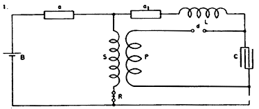
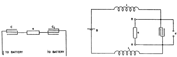
Other
arrangements of apparatus with open secondary for exciting sensitive
device.
In this plan (4.) the secondary S is connected to the terminals of
sensitive device a through a small condenser CCX. A very small
condenser is sufficient to cause the excitation.
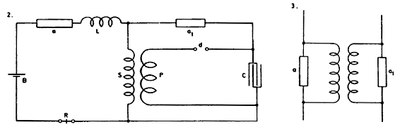
This is a modified arrangement (5.) there being only one condenser
and besides a very high self-induction around device a to provide
for initial excitation when device a is originally of practically
infinite resistance. The relay R may be placed around device a
instead of self-induction l.
In the diagram below (6.) is shown a manner of connecting apparatus
to a circuit Lx C, which is adjusted to be in synchronism with the
primary vibrations of the oscillator and excites device a.
Again in Diagram 7. a special synchronized circuit is done away
with, the secondary itself being adjusted to the primary vibrations.
The plan adopted in New York apparatus
of winding secondary and primary on a large drum (8.) serving at the
same time as table is best. Tuning is easy, apparatus cheap, a large
amount of copper may .be easily placed in the synchronized circuit.
Colorado Springs
Aug. 15, 1899
Change of secondary of oscillator to adapt it to the jars. Capacity
for one tank 36 bottles 0.03816 mfd. Two sets of tanks, 8 in each,
give in series a total capacity of 4 tanks that is 0.15264 mfd.
Now resonance of present secondary 5280 feet was obtained with total
capacity of 6 tanks instead of 4. Reducing the figures for length we
should have for smaller length a
capacity larger in proportion
 , or 1.11 that is instead of 4
tanks we should have
had 4.44 for 5280 feet. The required length for 6 tanks capacity.
This length would be , or 1.11 that is instead of 4
tanks we should have
had 4.44 for 5280 feet. The required length for 6 tanks capacity.
This length would be
With this length the oscillator will require same capacity as extra
coil and good results may be expected.
Colorado Springs
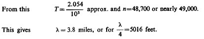
Aug. 16, 1899
Owing to high self-ind. of secondary of W.T. and large ratio of
transformation and also great inductive drop in supply transformers
(which are poor) of inadequate capacity
desirable to work with two circuits as adopted in small size
oscillators with mercury break.
Various advantages are thereby
secured chief of which: double break number, smaller resistance in
gaps and increased capacity of W.T. for charging condensers.
Connections may be as illustrated in I and II.
This connection shows well with small oscillators provided the short
circuit of secondary of supply transformer avoided.
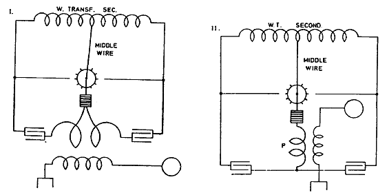
Colorado Springs
Aug. 17, 1899
In the working of transformer as before illustrated I. or II. the
short circuit of secondary is an inconvenience which is overcome by
having a few teeth at a good distance, but this diminishes the
number of breaks which it is practicable to secure. Another way is
to adopt a process also successful with small oscillators — of
charging the condenser, next disconnecting the same and finally
discharging. But this has also the disadvantage of reducing the
number of breaks.
Plan here illustrated seems free of these objections:
Here the short-circuit is avoided by the use of self-inductions Ly
and L^ which must be well insulated to stand high tensions. A single
self-induction inserted in the middle wire may also be used with
like effect.
Colorado Springs
Aug. 18, 1899
The best result with apparatus at command, that is, 3 supply
transformers, West. Tr. and condensers newly constructed is obtained
by employing two dielectrics giving total capacity of condensers
equal to that of four tanks. This allows working with 22,500 volts
safely.
The results will probably be the same with 45,000 volts connection
and 4 dielectrics but then capacity is only one tank and sparks in
primary are longer and more difficult to control.
With connection illustrated before (Diagr. I or II) it is also
practicable to work whh 45,000 volts total by connecting the tanks
on each side in a series so that capacity of each of the two
alternately working circuits is equal to that of two tanks. That is
2x0.03816=0.07632 mfd.
With one primary turn this gives
Colorado Springs
Aug. 19, 1899
Previous experiments showed in a number of cases good results with
connection and quantities as indicated: Capacity in primary circuit
6 tanks on each side; 1 turn primary about 3/4 of self-ind
regulator.
From reaction of capacity on secondary of W. Transformer it was
probable that more capacity was required, but the transformer was
overloaded when more tanks were joined.
With 22,500 volt connection the overload was very marked and lamps
would go down 50%. When the connection was changed to 15,000 volts
the lamps instead of falling would go up some 35% — 40%. No other
change in capacity or otherwise was made and this showed that effect
not merely due to an interaction and self-induction and capacity but
that the e.m.f. was also a determining factor.
With the first connection effects were brilliant, sparks in gap 8—11
feet according to charge and adjustment. Above considerations led to
changing to two turns primary. Capacity first 1 1/2 tanks on each
side. e.m.f. on transformer 22,500 V would go up possibly 25%.
Capacity was gradually increased to 3 2/3 tanks on each side when
with Regulator all out the effects were best. The rise of e.m.f.
about 35—40%. The sparks were curiously fierce, no direction
seemingly, darting pass terminal l.
(Here fire started on coil).
Colorado Springs
Aug. 20, 1899
Exp. with oscillator secondary 29 turns continued to ascertain free
vibration more exactly. Connection 2 series on each side, 4
dielectrics, total capacity 1 tank. Tension on Westinghouse
Transformer 30,000 volts approx. Spark gaps outside about 3" each,
inside one turn. Results on the whole less satisfactory showing
clearly that difficulties increase as tension becomes greater.
Middle box on one side broke down, sparks following through the
mahogony frame to a screw and jumping from this a distance of 4".
This can be only
due to rapid vibration and suddenness as tension on that box only
15,000/2 volts. There
are some doubts as to the distribution of e.m.f. in condensers in
series when vibration takes place. Strong (probably inductive) drop
on supply circuit (exceptionally so).
Observation: When lamps increase strongest on supply circuit then
spark will not jump over the gaps, showing that then e.m.f. on
secondary of W.T. smallest.
Connection was changed to that indicated in sketch for the purpose
of avoiding effect of short circuit of secondary of W. T. through
primary arc. Absorbed energy was great. Sparks on switch serious.
Lamps would go up very much when arc would break through. But
general results not satisfactory. The condensers directly on W.TS.
take strong current.
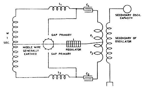
Colorado Springs
Aug. 21, 1899
Other experiments with oscillator secondary 29 turns. Simply spark
gap. Connections used:
Plan illustrated in first diagram was adopted to obtain double
number of breaks with same disk and securing other advantages. Also
to better utilize W. Transformer. It was found that when one side on
it worked remarkably well, sparks about 4 feet. The tension on each
half of transformer being 11,000 volts approx. when both parts on
interaction hurtful. The chief drawback being short circuiting of
secondary.
The arc was snappy and loud indicating short circuit and
rapid vibration through wire W. The secondary discharge was thick
but spark not long about 3 feet. All tanks were in on
either side and the transformer charged them full when separate.
When both parts on evidently the secondary of W. T. was overloaded.
In arrangement illustrated in 2 short circuiting was largely
overcome but the short circuit of secondary of W. T. remained the
same. The results were similar no matter in what direction both
primaries were connected. The necessity of overcoming short circuit
in both arrangements became soon more and more important.
To improve — arrangement illustrated in Diag. 3. was used. It proved
itself more economical but the amount of energy was limited. The
hurtful short circuit was entirely obviated and the lamps were less
affected.
Colorado Springs
Aug. 22, 1899
Arrangements for telegraphy tried. In these the chief point was to
keep one end of secondary spool open so to allow full rise of
pressure on this end. The sensitive device, one of the before
described, excited fully resistance 12 ohms approx. Not excited over
100,000 ohms.
In Diagram 1. first experimented with, a disadvantage was found to
exist: namely, the receiver R was operated through the break device
d. This inconvenience was done away with in arrangement illustrated
in Fig. 2. which allowed more sensitive-adjustment of Relay R and
the apparatus worked better.
Capacity of condenser was varied up to
20 mfd. with changing success. Best results seemingly with small
capacities up to 1 mfd. Secondary about 4,000 turns, primary Lamp
cord No. 10 turns 28. The apparatus responded freely to small pocket
coil at a distance of several feet with no capacity attached and no
adjusted circuit. Consequently will go at great distance.
In these arrangements, as in the previous ones involving the same
principle, the effect on the sensitive device is accumulative and a
difficulty arises that namely the sensitive device will not readily
de-sensitive. By inserting large resistance r in circuit with
receiver R this effect upon the latter is largely reduced as the
current through receiver and device is kept to a minimum.
By
adjusting speed of rotation of sensitive device the inconvenience is
also overcome.
Colorado Springs
Aug. 23, 1899
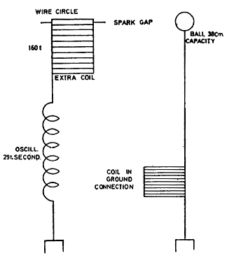
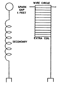
Experiments with new extra coil placed in center of primary. The
spool 75" diam., 12 feet high, 160 turns in all. 120 turns wound
close together in the adjacent grooves and 40 turns the upper ones
at three times that distance, that is, two empty
 grooves between
each two turns. Breaks on two sides alternately approximately 2,400
breaks per sec. On top (free end) ball of 38 cm. capacity. Resonance
was obtained with 5 2/3 tanks on
each side, one turn primary, self-induction in box 4 turns. grooves between
each two turns. Breaks on two sides alternately approximately 2,400
breaks per sec. On top (free end) ball of 38 cm. capacity. Resonance
was obtained with 5 2/3 tanks on
each side, one turn primary, self-induction in box 4 turns.
Gaps
were 1 1/16 on each side plus gaps in box 2 turns. Tuning remarkably
exact, 1/8 turn of self-ind. box reducing the effect very much. When
exactly 4 turns in box, sometimes streamer 8 foot long would shoot
out from a defective spot on wire. The ball on top reduced streamer
capacity and prevented streamers from coming out all along the top
turn as usual. The spark gaps work extremely well, loud explosive
character indicating good vibration.
Such sparks are always noted
when secondary well tuned. The system worked economically, the lamps
in supply circuit not falling at all. The earth connection now was
taken off and oscillator of same period — (the secondary 29 turns connected). Both had now
same period, the secondary and the extra coil. On first throw of
switch a spark darted to roof above from the ball and the cord
caught fire. Fortunately, it was extinguished before doing damage.
This accident showed that better provisions against such an accident
have to be made. The roof to be fixed with a guard of wire gauze
which would prevent the wood from catching fire through sparks
darting up. As it was dangerous to work further without guard
against such an accident another ball 38 cm. supported on high was
connected to earth and placed at varying distances from the ball on
the end of the extra coil.
The sparks jumped from the upper turn of
the coil to the Earthed ball and sparks of seven feet were easily
obtained. It was evident that the distance could be much increased
but this was deemed hazardous. As it was the sparks of seven feet
were probably the longest obtained from such large balls or surfaces
of such small curvature.
The connection of the primary circuit was now changed, two turns
being used in series. This reduced the period to one half and it was
thought that this would respond to the fundamental note of both
secondary and extra coil. Experiments were disappointing for the
display was not remarkable, the sparks were up to four feet long but
much thicker and whiter. I believe that the true vibration was not
struck but skipped.
As tiftie pressed, further experiments with the
view of ascertaining the fundamental note were postponed and the
first connection with one primary turn again made. Both balls were
now connected in multiple to top of the coil and to the upper rod of
a spark gap, the lower rod being earthed. There was no danger of
setting fire in this way. The display was remarkably noisy. The
sparks were up to 14 feet long, snapping quick,-explosive and very
white.
Sometimes streamers would shoot out fully 11 feet. Often
several sparks at once. No particular direction in striking. The
capacity in the primary circuit was varied up to 8 tanks on each
side. Always striking effects. The ground wire had no capacity and
no sparks were seen on arresters but before, with only one ball and
no streamers, sparks of 5/16" were drawn from water pipe in distant
room.
Colorado Springs
Aug. 24, 1899
Experiments with new extra coil and oscill. secondary 29 turns
continued. The ball on top was disconnected and a bare copper wire
run around the upper rim of the coil to produce streamers. Capacity
in primary circuit on each side was 5 2/3 tanks with 4 turns
self-induction box in. It was not advisable to work because by the
throw of switch some streamers would dart up to the roof a distance
of 12—13 feet. The other ball used in previous experiments was
placed at a distance of 11 feet from coil and also it was
unconnected — except that it had a wire of about 8 feet hanging from
it —the sparks would fly to it from the rim of the coil.
A curious feature is that the streamers are very sudden, explosive.
This is due probably to the suddenness of the break. Occasionally an
unusually long streamer would
shoot out. This probably owing to resonance of break or temporarily
short circuit over break, probably the former cause responsible.
Desirable either synchronous break as worked in New York, or a very
rapid one. The speed of motor is to be increased to double for this
purpose.
Coil was disconnected from the oscillator and connected to the
ground. The period corresponded to that of the primary with 7 tanks
on each side, no self-induction. 5 2/3 tanks, 4 turns, and 4 tanks
and 9 turns. Thus 3 tanks made only a difference of 5 turns on self.
box. With four tanks tuning wonderfully close, twice it was missed
before finally located.
(The roof of building was fixed today, cords done away with)
Colorado Springs
Aug. 25, 1899
Experiments continued with extra coil on wooden frame 12 feet high,
6 feet diam., 160 turns No. 10 wire. A bare copper wire was
supported on top, the wire forming a circle not closed of about 8
feet diam. Another copper wire was supported 4 feet below and at a
distance of about 13 feet, all around the diameter of circle being
approximately 34 feet. This circle (also not closed) was connected
to ground.
Very powerful streamers were produced sometimes extending
the full distance between the wire circles, but still they showed
tendency upward in spite of presence of ground circle. Often sparks
would pass in curved paths between the two circles. During the
display no sparks on arresters, small sparks in adjacent room from
water pipe. Capacity on each side from 5 2/3—7 tanks.
Longes
streamers with former value. The circle of 8 feet diam. was then
taken down and another one about 10 feet placed on top of coil.
Streamers now showed some tendency to pass to grounded circle.
Sparks to the latter more frequent and brilliant. No play on
arresters and small sparks in adjacent room as before.
One of the balls was now connected to the ground but although sparks
of eleven feet jumped to same no sparks on arresters. The vibration
was evidently slow, that pertaining to extra coil and harmonics in
earth wire from ball did not preponderatingly appear.
Colorado Springs
Aug. 26, 1899
Experiments with oscillator secondary 29 turns and
extra coil last described continued.
The alternate motor was put on 200 V with self-ind. coil in series,
latter regulated so that motor could drive disk of break with twice
the speed, that is 4200, the speed of
motor being approximately 2100. This gave, since disk" had 20 teeth
and two alternately
working breaks,  breaks per second. breaks per second.
In the first trials connections were made as in sketch. The spark
gap between wire circle on top of extra coil and ball supported was
8 feet.
Sparks passed readily and the display on arresters was remarkable.
Thick arcs joined the arrester contacts on both lines and jumped
also through one of the choking coils. This was the strongest effect
so far on arresters.
A choking coil was now inserted in ground connection to see whether
by lengthening the period of the earth wire the sparks on the
arresters would be diminished. This coil was 34" diam. wound with
one layer wire No. 16, thick rubber insulation (layer 10" high) 50
turns. This coil did not weaken the effect much probably because
frequently sparks would jump between the turns.
Otherwise it was
surmised that the vibration of the secondary itself with the extra
coil might be responsible for most of the e.m.f. generated between
the ground and line. Singularly, despite this strong effect as
evident from arresters but very small sparks were drawn from water
pipe in adjacent room, this seemingly indicating that in this
experiment the earth acted as a nodal region.
The conclusion from these first experiments as to the efficiency of
the break was that double number of breaks decidedly better. Nor did
it short circuit the transformer more because of the increased
number, but on the contrary less as far as could be judged from the
lamps on the supply circuit which went up as the switch was thrown
in.
It was evident, furthermore, that the large circle of wire which was
before supported above the secondary and grounded, strongly
interfered with the action on arresters because it allowed local
vibration which was not effectively transferred to the ground and
the air.
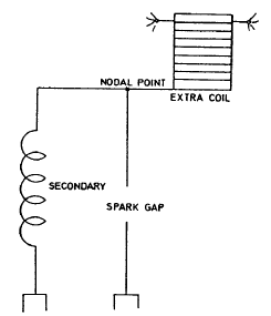
To decide surely whether, and to what extent the long waves were
responsible for the difference of pressure evident on the plates of
arresters, the secondary and extra coil were connected as in sketch.
In this connection only long waves could be effectively transmitted
upon the ground. It would have been desirable in this and previous
experiment as well to take off the wire circle and substitute a ball
on top of the extra coil but this being inconvenient the circle was
left.
As the extra coil had now only a small initial pressure the
e.m.f. obtainable in the spark gap was much smaller and the gap was
reduced therefore
to 4 feet at which distance sparks readily jumped. The play on
arresters — though weaker
— took place nevertheless, this important result showing that waves
3—4 miles long could produce these e.m.f. sufficient to cause the
sparks to pass between the plates of the arresters. Now it is
important to consider: is the earth a nodal region or the crest of a
wave (that is, the region immediately adjacent to point of
attachment of secondary to ground).
If a nodal region then the e.m.f. set up at the small distance of 60 feet separating the point
of attachment and the ground of lightning arresters was only a small
part of the total
e.m.f. But if a crest then the e.m.f. set up and causing sparks was
nearly the total e.m.f. produced by the apparatus. If a nodal region
near the point of attachment of the secondary, then at a distance of
about 4000 feet there must be a strong effect, but if a crest, then
at that distance there would be no effect. This is to be decided by
further observations.
The connection was now changed to that
indicated. It was thought that both vibrations would cooperate and
produce a stronger effect, but it was at once evident that so long
as streamers (which were about 10 feet) formed on top of the extra
coil the effect must be smaller, since all energy came from the
secondary and the streamers caused loss. A condenser ought to be
used instead of a gap to make such an arrangement most economical.
Although owing to nodal point the length of spark in adjustable gap
was small, the display was strong on arresters, but not nearly as
strong as when the extra coil was entirely left off. In the latter
case the action was very rigorous so that often flames would form on
arresters showing short circuit of dynamo. Also the other choking
coil would break through. Evidently then the extra coil did not in
this instance prove useful in intensifying vibration contemplated.
Experiments continued: extra coil was
now lowered 2 feet nearer to ground, distance now being about 4 feet
from floor and 5 feet from ground.
Capacity 5 2/3 tanks on each side in primary. The transformer (W.
Co.) works very well (22,500 volts). The lamps go up 35—40% when the
arc does not break through, the gap being made large for this
purpose, and when the arc breaks through they still rise
slightly above normal.
The gaps outside 1 1 /4" each approx. Inside
1 1 /2—2 turns. Streamers produced were still more powerful being
made so owing to approach of secondary. They would dart out to a
distance of 12 feet sometimes.
Important. Strong arcing on arresters, although no spark would pass
to the ball used before, which was placed at a distance of about 9
feet. Could the sparks be produced by static induction upon wire
through the air and not chiefly by conduction through earth?
To test
this a coil 50 turns referred to before was inserted in the ground
wire of the lightning arresters. It was expected that it would
weaken discharge across, but did not probably because the current
was small and the choking action likewise for this reason.
To see whether there is some current passing through the earth wire
to the line, another coil was placed in inductive relation to the
ground wire coil and strong sparks 3/8" were obtained on former.
Sparks, lively 3/8" approx., were also obtained from coil P. Note:
Sparks to ball sometimes, at other times streamers would dart past
the ball. The streamers horizontal when sudden, when switch was held
longer they would waver. In last experiments only half of wire
circle on top of spool was used.
Colorado Springs
Aug. 27, 1899
Older plans experimented with and modified arrangements of apparatus
for wireless telegraphy further considered.
These connections used to relieve the sensitive device from the
strain of the battery after excitation. The necessity of doing this
leads to the reconsideration of an old plan experimented with in New
York which consists of placing the sensitive device between
condensers in circuit so that each time only one current impulse can
pass through the device.
This is illustrated in a general way in the
little diagram below. The battery strains the device a through the
condensers C Ct but when, upon the device a becoming excited, the
condensers are suddenly charged the current impulse caused by the
charging automatically stops. It is then necessary to reverse the
mains, or discharge the condensers to make the apparatus ready for a
second operation. This plan allows use of very high pressure on the
sensitive device which should be of great resistance.
Plan in last diagram illustrated consists of raising, by means of
inductances l l1 condenser C and break device d, the e.m.f. of
battery B so far as needed to bring the device a to the point of
nearly breaking down. The quantities should for a better result be
adjusted as usual. Both relay coils R R and inductances l l1 are
placed symmetrically.
Colorado Springs
Aug. 28, 1899
Experiments with oscillator, secondary 29 t. in series with extra
coil before used (160 t) were continued tcday and showed the
following: Capacity in primary being from 5 2/3—8 tanks on each
side, varied to observe shifting of nodal point, play on arresters
and behaviour of streamers and spark discharges.
A half circle of bare wire on top of extra coil was left and in
addition a larger half circle of bare copper wire (No. 14) was
supported on wooden strips 4 feet below the former half circle. Both
the bare wires were connected to the free end of an extra spool. The
lower half circle was 9 1/2 feet away from a circle of the same bare
wire which was supported on oscillator secondary frame and formed
the terminal of the secondary.
Abundant sparks and streamers were
produced. The play on arresters was also observed at each throw of
the switch. The rain and lightning were just beginning. Magnificent
intense white light witnessed below Pike's Peak, something very
unusual. It resembled a white hot silver furnace. The lightning on
the mountains was very frequent and the discharges of unusual
brilliancy. Twice a curious phenomenon was noted. Lightning striking
in one part of the mountains from cloud to earth, there was seen in
another part a few miles away from a high peak a lightning discharge
which to all appearances came from the peak to the cloud.
The
discharge was much thicker at the root and branched out towards the
sky spattering itself in many branches and disappearing in fine
streams. The astonishing phenomenon was witnessed a second time and
subsequently, though there was much uncertainty about the direction
in the latter cases; a few times a similar discharge took place from
other peaks. Is it possible for a discharge to go from Earth to
cloud? As far as the visual impression is concerned there can be no
doubt.
The discharge in all cases followed a preceding lightning
discharge in another region, and apparently from cloud to earth.
Perhaps it can be the effect of an intense vibration started by the
first discharge which results in another discharge towards an
oppositely charged cloud. The clouds were unusual in configuration
and grouping. A large portion of the sky was quite clear. The wind
at times was very strong. An instrument by its constant play
indicated strong electrical disturbances through the earth, even
when there was no display of lightning as far as could be seen or heard.
After some time the experiments were continued and presently it was
observed that the usual sparking on the arresters was no longer to
be seen when the switch was thrown in. The only change made was to
take the upper half circle off leaving only the lower one.
This gave
a smaller streamer surface and consequently longer streamers. The
display was fine. In order to see whether the upper half circle of
bare wire was responsible for sparks on arresters the wire was
replaced but still no result. Then it was thought that other causes
for the sparks not appearing were responsible and everything that
could have the slightest bearing upon this was investigated. Still
nothing was arrived at. The sparks did not appear no matter what
change was made in the adjustment of the vibratory circuits. What
could be the cause?
The only explanation at present is that the roof
was rendered slightly conducting (although there was little rain in
this locality) and that this produced the change. Important to find
out. Observation: The lightning lighted two houses about two miles
away.
Colorado Springs
Aug. 29, 1899
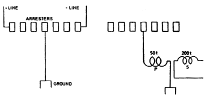
Experiments were made with receiving apparatus comprising an
oscillator with mercury break and two devices of the kind before
described. The oscillator was of a later 2000
pattern, mercury break by 2000 rev. per minute gave x 24=800 breaks
per second,
60 there being 24 teeth in the pulley. The condenser in the
instrument was 1 mfd. approximately. The instrument was used as a
sender and the experiments were intended to test its efficiency as a
receiving apparatus.
Accordingly, the connections were made as in
sketch, the method of magnifying by oscillating transformer being
made use of to increase sensitiveness. As far as practicable all
connections and parts of instrument were used.
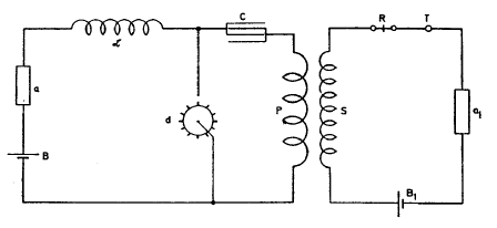
The connections of primary circuit including break
remaining the
same, only a battery B. (1—4 cells dry O.K.) and sensitive device a
being inserted instead of a generator. In the high tension secondary
were connected a receiver R (relay), telephone T, battery B, and
another similar sensitive device a1. The motor was driven from a
small direct current generator which in turn was driven by the
alternate current motor usually employed to drive the break disk of
the large oscillator. This apparatus was extremely effective, merely
the addition of small capacity on a was sufficient to make the
receiver respond. Evidently this effectiveness is due to the
efficiency of the oscillating transformer and excellent working and
high frequency of the mercury break.
Experiments were continued for a short while with oscillator and
extra coil. The frame of the secondary was repaired and a board for
connections of the transformers put in place and other work took
most of the day, it being late when the investigation was resumed. A
netting of wire gauze (iron) had been placed around the opening of
the roof to diminish danger of inflaming the building.
But on the
first throw of the switch the streamers and sparks darted against
the netting a distance of about 12 feet and sparks were seen to go
from netting on to the wooden structure of the roof. It was
advisable to stop work and the roof was removed. Now the ball on top
of the extra coil was connected to the latter by a wire No. 10,40
feet long, very heavily insulated with tape over the rubber
covering.
One turn on the outside and nearly another complete one in
the inside were made and the end of the wire connected to the ball.
The latter could not be lifted up and the experiment was tried with
the ball in place. The streamers now appeared on the ball copiously
when the current was turned on, their tendency being to go straight
up into the air.
The
longest were only about 4 feet as it was deemed unsafe to strain the
apparatus higher until further provisions for safe working were
made. The lightning arresters were observed but no sparking. This
showed that the absence of sparks was not due to rain or moisture as
was concluded yesterday, since the weather was very warm and dry.
Colorado Springs
Aug. 30, 1899
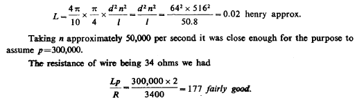
Experiments were resumed with resonating coil to be used in
connection with receiving apparatus. The coil was wound a week
before on a drum 25 1 /4" diam. of bicycle hoops and a thin board,
the idea carried out before in New York being followed to make the
drum with coil serve, at the same time, as a table for instruments.
The drum was 3 1 /2 feet high, only partially wound on upper part.
The wire was ordinary magnet wire No. 20, 516 turns. The
self-induction was approximately calculated from the following data:
diameter of drum 25 1 /4" or 64 cm.; length of wound part 20" or
50.8 cm.
The coil was now tuned with oscillator in response to a somewhat
higher note with small capacity on free terminal, the other being
connected to the water pipe. Sparks of 3/4" were obtained while from
the water pipe alone a very minute spark, scarcely perceptible,
could be obtained. Induction from primary being carefully
eliminated, the sparks were still 3/8" long and white.
Colorado Springs
Aug. 31, 1899
Experiments were continued with the extra coil and secondary
conditions as before. The ball in the center was connected again to
the top of coil and elevated a little above the roof, the latter
being opened as wide as possible. The experiments were begun in the
afternoon while the Sun was very bright. Scarcely any streamers from
the ball could be seen but occasionally sparks would go to the roof
from the center wire leading to the ball.
The distance was 12 feet. There was a pronounced tendency in the
sparks to fly to the roof which might have been due to dampness of
the latter owing to rain the day before. During
the few trials which were cut short because of the danger
threatening from the sparks, the lightning arresters were observed
but no spark was noted. In the forenoon the mains were tested and it
was found that one of them was fairly grounded which to some extent
also made the other defective. This probably was the reason why the
sparks no longer appeared on the arresters.
A number of curious observations were made during the trials with
the elevated ball. A fly was seen to light on the top of the ball
and when the switch was thrown in the insect disappeared evidently
thrown off with great force. Another such insect alighted on the
under part of the ball, and the current being thrown in just about
at the moment when the fly started off, the fly was seen to fall
from a distance of about one foot from the ball straight down to the
floor, evidently killed in the flight.
Still more curious it was to
see a moth at a distance of fully eleven feet from ball, near to the
wooden frame fall straight down as the switch was thrown in. The
strongly electrified ball evidently exercises a strong attraction on
a small insect which is drawn towards it every time the ball is
electrified. This was repeatedly tried.
An observation less amusing but more useful was that when the ball
with its circuit were well tuned and no streamers appeared, owing to
good insulation of leading cable
— there was a decided tendency to break the jars in the primary.
Evidently, when there are no streamers the vibration is effected
with lesser loss and hence there is a great rise of e.m.f. reacting
upon the primary. This at least appears the most plausible reason
for the phenomenon observed.
Light seems to interfere decidedly with the streamers from ball and
wire and it is also unmistakably noted that the noise of the
discharge is lessened when the sunlight falls upon the apparatus.
Spark gaps were established in a number of ways as by connecting
both coil and secondary to ground and each to one of the balls and
establishing a spark gap between the latter.
Finally the ball was again connected as before and elevated, a point
being first placed on top to facilitate formation of streamers. It
was curious to observe that the streamers were carried away
horizontally, and eventually blown out by the wind. The resonating
action was strong but the length of the streamers could not be
estimated. From the leading cable the discharge would sometimes leap
to a distance of at least 10 feet.
The action of the wind suggests
the idea of preventing the formation of wasteful streamers by a
current of air.
Back to Contents
|