|
The subterranean chamber is a complex assembly with no immediately obvious reason for the complexity. For a control group, the subterranean chamber assembly was removed and a straight pipe with a “tee” was installed (see Figure 12). The pump still functions with similar output. The primary differences being the presence of a large reverse pulse at the reservoir and the output flow was more erratic. I was surprised to discover that the subterranean chamber changed most of the fluid‘s shock wave into a vertical compression wave in the cement assembly. In his book, Chris Dunn states, “The equipment that provided the priming pulses was most likely housed in the Subterranean Pit.“2 (pg 220)
The equipment
may well have been water-hammer and from the pit it came.
It seems possible that the subterranean chamber can shake the whole pyramid and can elevate water to any part of the Giza plateau - pyramid peaks included.
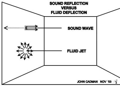
FIGURE 13. The Fluid
Dynamics and Acoustical Dynamics
The sound wave striking the
perpendicular surface reflects the majority of the pulse back
towards the source. When the fluid jet strikes a perpendicular
surface, it spreads in a 360° pattern perpendicular to the jet. The
subterranean chamber incorporates fluid dynamics and acoustical
dynamics.
The various water flows can be demonstrated by varying which ink injection ports are open.
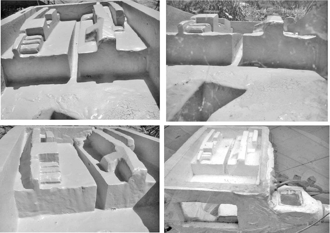
FIGURE 14. Westward
Views of the Fluid Dynamics Model Looking towards the step gives a perspective of the fin arrangement. (Upper Right) Looking through glass eastern wall with pit in foreground. (Lower right) Glass eastern wall can be seen as well as glass topped ante chamber.
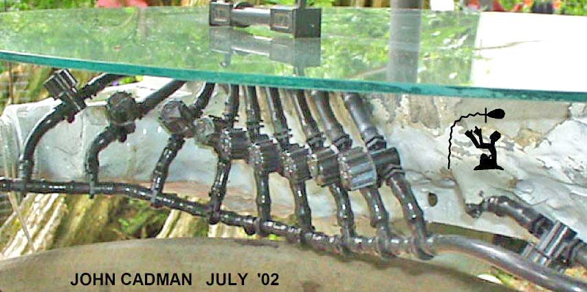
FIGURE 15. The Fluid
Dynamics Model with Glass Top and Ink Jets
The glass topped fluid dynamics model
showing 10 of the 25 ink injection valves. By placing the injectors
at strategic locations, the exact fluid dynamics were able to be
established. Running the glass topped model in the pump/pulse mode
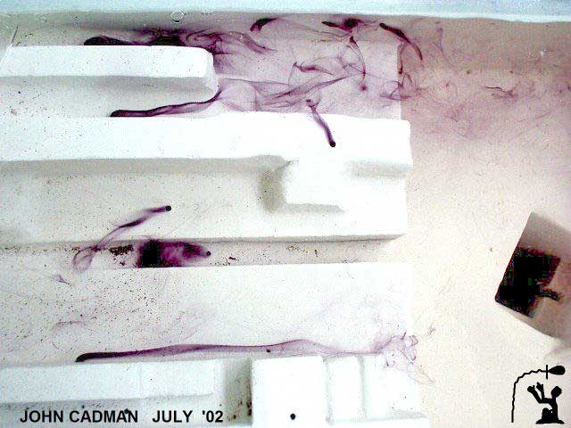
causes the glass to immediately shatter. (Right) Ink being injected
into seven ports on the step show the precision and beauty of the
fluid design.
The erosion patterns confirm the existence of a tunnel from the pit to the Nile.
FIGURE 16. Water
Erosion in Subterranean Chamber (Left) The antechamber before the subterranean chamber shows significant erosion on the ceiling where trapped air allowed turbulence and splashing of water. Photo: Edgar Brothers (Right) Reconstruction of a fin shows extent of erosion in finned area. The builders always used angular sufaces as opposed to the curved surfaces that are present in the fins.
The fin on the right shows more extensive damage. Photo:
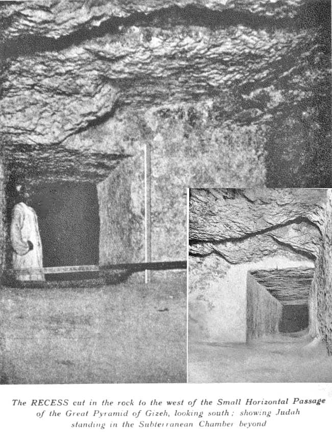
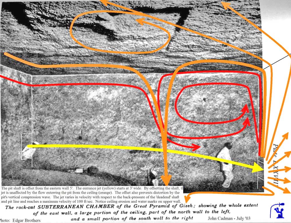
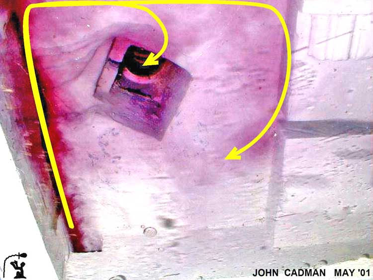
FIGURE 17. Looking
into Subterranean Chamber from the Antechamber (Left) The entrancer jet (yellow) shoots from the horizontal passage across the subterranean chamber to the entrance of the “dead end“ shaft (red X). The “dead end” shaft is a water output. The left wall is continuous from the antechamber through to the “dead end“ shaft and functions as a guide. As part of the jet strikes the far wall, it is deflected up and to the right (orange). (Right) The entrance jet is shown shooting across the room. Because the pit is offset from the far wall, the ceiling-to-pit flow misses the jet. Extensive erosion on the ceiling exactly matches the flow patterns. The area at the top of the picture appears to be cavitation damage from the extreme low pressure rarefaction wave. Photo: Edgar Brothers
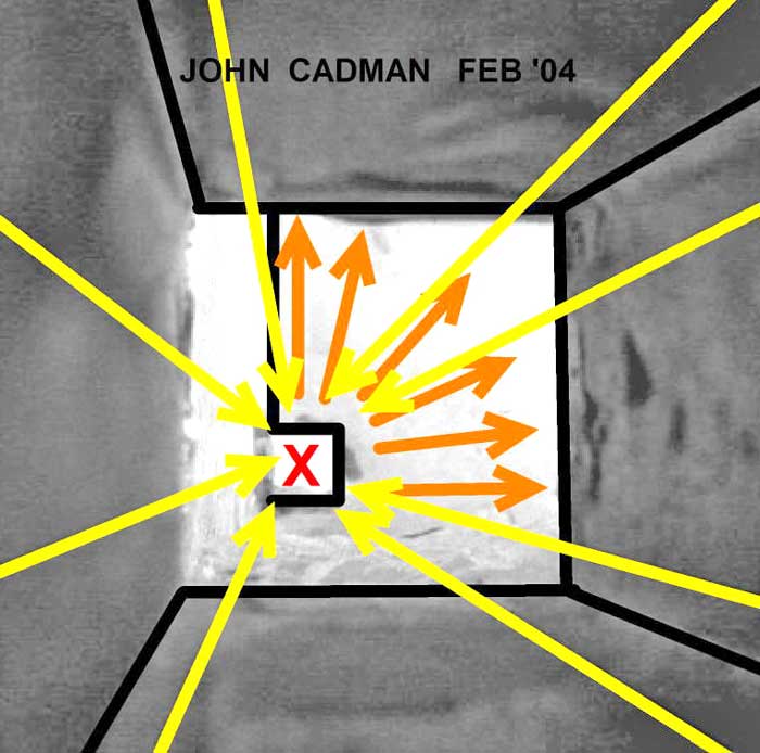
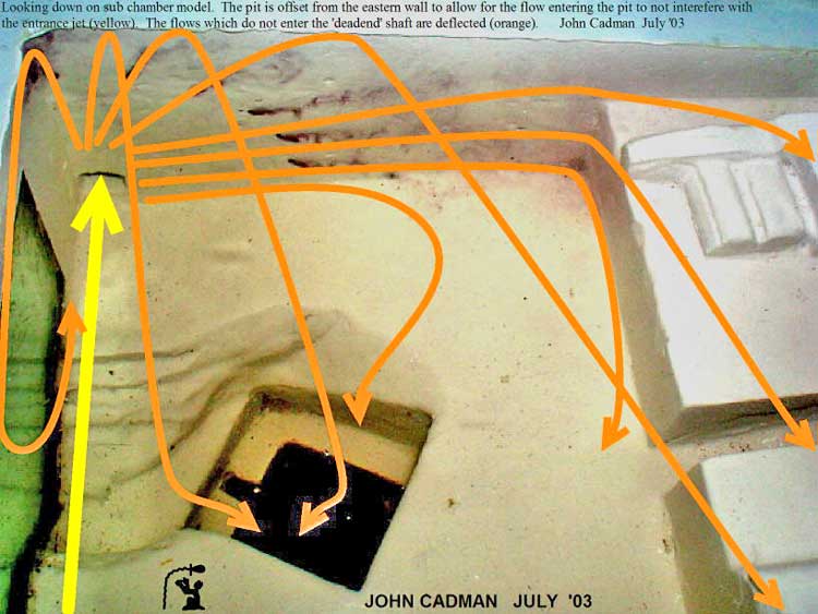
FIGURE 18. Fluid
Dynamics in the South Eastern Quadrant (Left) Looking down on model shows ink being injected in entrance jet. The entrance jet shoots across the room where part of the flow is deflected by the far wall. (Right) Ink is being injected in six ports around the “dead end” shaft. The yellow entrance jet shoots towards the entrance of the high pressure output. The orange arrows show the deflection around the “dead end” shaft.
Notice how there is a flow from the ceiling down into the pit. The pit is offset from the eastern wall to prevent this ceiling-to-pit flow from interfering with the yellow entrance jet. This completely explains the pit’s offset from the wall. The sloped area at the top of the pit is erosion caused by a major flow into the pit.
At Giza, this area has been filled with bricks to accommodate hand-rails.
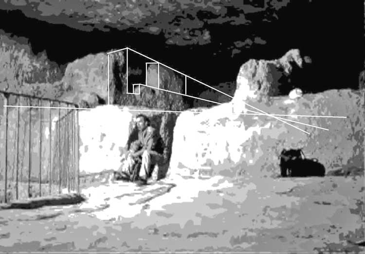
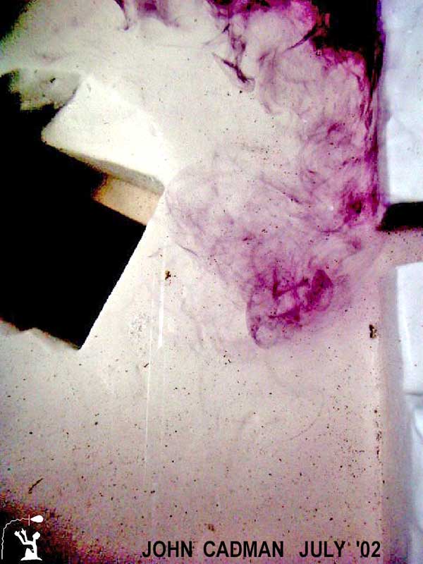
FIGURE 19. Fluid
Dynamics at the Step Channel (Left) Looking down on the step face as well as the pit, the ink shows the flow running along the face of the step. As it arrives at the step channel this flow is diverted. Erosion on the floor exactly matches this pattern. The pit’s diagonal offset is exactly aligned with the tunnel to the Nile. (Right)
Ink is injected into the step channel showing flow direction and that it diverts the face flow.
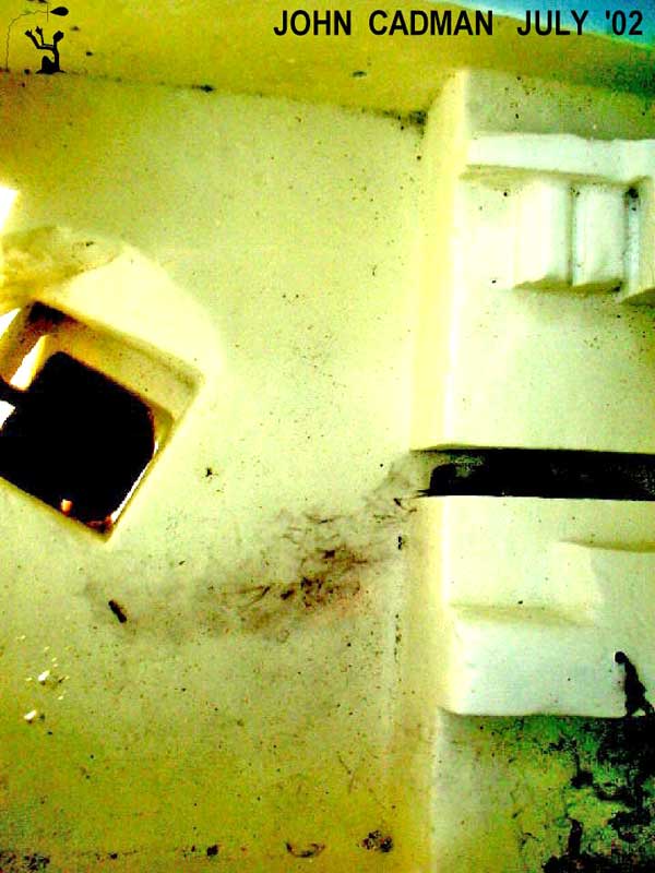
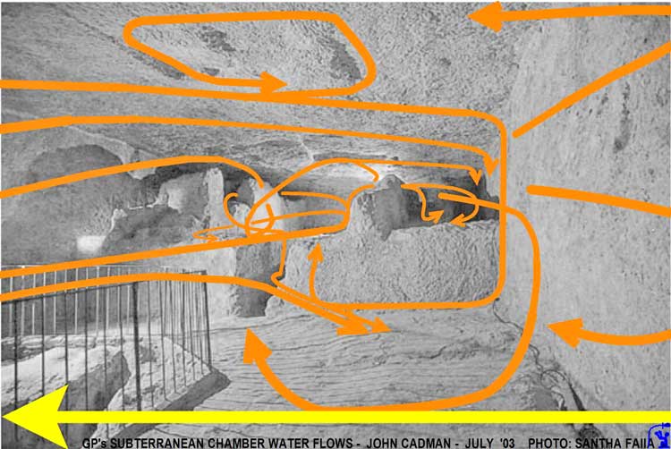
FIGURE 20. Fluid
Dynamics in the Western Sector In the subterranean chamber looking at the step and the primary flows. There exists significant erosion on the floor, walls, and ceiling that exactly matches these flows. Designing this room for the complex three dimensional fluid dynamics would have been a monumental task, not to mention the simultaneous acoustic dynamics. Photo: Santha Faiia
FOUR YEARS OF OBSERVATIONS
WELL SHAFT and GROTTO
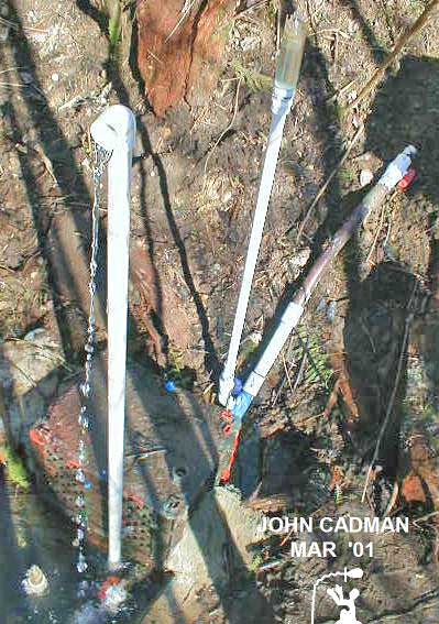
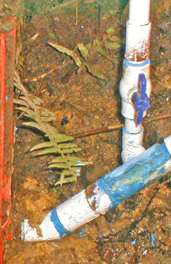
FIGURE 21. Running
Model with Well Shaft Open
(Left) The “pulse generator” model
cemented in place and running. Water is being output through the
”dead end” shaft line. The well shaft is the second vertical line
and has a clear plastic top where the grotto is located. The clear
grotto allows viewing of the reverse pulse height. The descending
passage is the brown and white pipe. (Right) The well shaft is in
operation because the valve is open. The output through the “dead
end” shaft has decreased by 68% as compared to when the well shaft
is closed.
In the circulating pump configuration, the well shaft reduces the efficiency by 29%. More significantly, in the elevating pump configuration, the well shaft reduces the efficiency by 68%. If the well shaft was incorporated in the original pyramid design, as I believe it was, then the pumping efficiency was not of prime importance. If the pumping efficiency was not of prime importance then the pump function is not the most important function.
This
raises the question, “What was the primary function of the
subterranean machine”?
FIGURE 22. The
Subterranean Chamber’s Compression Wave
The primary functions of the
subterranean section is to provide pulse for King’s chamber to start
the pyramid running or to create a "mass particle" in the Queen's
chamber.
Extensive sound testing has been done within this room by Thomas Danley2, John Reid10, Chris Dunn2, and others.
FIGURE 23. Simpler
King’s Chamber Design - after Chris Dunn
The five layers of granite beams above
the King’s chamber have been called “stress relieving” chambers, yet
they relieve no stresses. (Inset) A much simpler design similar to
the Queen’s chamber has equal strength. Did the builders forget
structural design as they moved higher up into the building? Did
they enjoy cutting and moving 70 ton ceiling beams?
Dan Davidson, a physicist, believes this pulse travels towards Orion. In 1997 Joe Parr and Dan Davidson traveled to Giza to conduct experiments. Joe built a special signal generator with an attached audio amplifier. Their object was to gain access to the pit chamber of the Great Pyramid where they believed that the energy bubble just enters the room. The room would amplify the effects of the generated signal and consequently control the bubble.”4(pg 162)
Might the energizing of the King’s resonating
chamber by the subterranean chamber be the means of turning on and
off the force field?
Adjusting the backpressure {67psi to 3360psi at Giza} also changes the water’s density thereby changing the compression wave’s velocity and frequency. This easily allows for fine-tuning of the lower assembly to create a standing wave in the subterranean chamber and wastegate line.
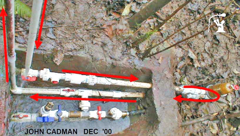
FIGURE 24. Testing
Multiple Options One of many pipe layouts used to find the best possible configuration for what is under the Giza plateau. Multiple valves were used to verify or negate possibilities, and this layout had 256 binary possibilities. A much simpler layout proved to be the best. To prevent damage to model's “dead end” shaft output, the pipe is stabilized by running it through a cement barrier and then doubling back towards the model.
This double back
layout is for convenience and does not reflect the Giza layout.
I’m still amazed by his original
vision.
The time required for the water hammer shockwave to travel from the valve to the end of the pipe and back, as well as the increase in pressure caused by the shockwave can both be calculated11.
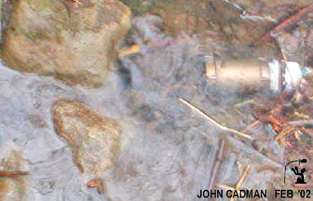
FIGURE 25. The Final
Wastegate (Left) Piston striking valve seat stops water flow instantaneously and causes compression of the water. The compression of the water causes high pressure compression wave and low pressure rarefaction wave. The low pressure rarefaction wave reopens the valve. (Right)
The submerged horizontal wastegate in action. It runs better once the valve is submerged.
FIGURE 26. The Valve
and Fluid Motion at Wastegate Fluid moving down wastegate line starts valve in motion. Valve accelerates towards valve seat. Closing valve stops water and causes water to compress. Compression wave and rarefaction wave heads back up the line. Low pressure rarefaction wave moves valve to open position.
No water moves past valve until
pressure wave returns. |