|
Chapter 4 - Electromagnetism
November 4, 2011
4.1 The Electromagnetic Field Equation
Scientists attempt to explain physical systems in terms of
mathematical models which describe and predict the behavior of the
system.
For example, Kepler explained the
movement of the planets with his three laws. In the same way, plasma
behavior is governed by the electromagnetic field equations, which
describe the motions of charged particles and their interaction with
electric and magnetic fields.
There are two components of the
electromagnetic field equations:
-
Maxwell's Equations
-
Lorentz Force Law
The two components act in tandem as a
feedback loop:
Maxwell's Equations determine the electric and magnetic fields based
on the position and motion of charged particles. They also determine
the interaction of the electric and magnetic fields if either is
changing.
The Lorentz Force Law determines the electric and magnetic forces on
a charged particle moving within the fields. This force will cause
each particle to move (accelerate) in accordance with Newton's Laws.
The changes in the positions and motions of the charged particles in
turn cause changes in the electric and magnetic fields.
Computer programs have been constructed to follow these interacting
phenomena in plasmas.
They typically involve a series of
steps, each representing a very short span of time. First, given the
state of magnetic and electric fields present and the mass, charge,
speed and direction of each particle, using the Lorentz Force Law,
the forces applied on each particle by the field values at its
position (x, y, z coordinates) are calculated.
The vector sum of the contributing
forces is calculated, and the resulting acceleration of the particle
moves it a small distance in some direction in the interval of the
tiny time step (Newton's Laws of Motion). This is accomplished for
the entire set of particles.
Then, considering the new coordinates and kinematic conditions of
each particle, Maxwell's equations are used to determine the values
of the electric and magnetic fields. After this, the program loops
back to the first step, where the electric and magnetic forces
acting on each particle are calculated once again using Lorentz Law.
The loop is controlled by the program's directing it to stop when a
defined condition is reached, such as a certain number of
repetitions, or if a certain value in the variables is reached,
changed, or exceeded, or an error of some kind is encountered, and
so on.
Once a set of starting conditions has been defined (number of
particles, their charges, masses, initial velocities, and a
description of the intensities of the assumed electric and magnetic
fields throughout a defined volume of space), the loop process above
might be outlined as follows:
-
Calculate all the forces acting
on each particle via Lorentz Law
-
Calculate new locations and
velocities for a very short increment of time using Newton's
Laws of Motion
-
Calculate E and B at each
charged particle's new location after this time increment
-
If an End-Loop condition is not
satisfied yet, go back to 1. and continue calculating
Other aspects can be added in for
greater accuracy or a better approximation to "reality", such as
collisions of particles, viscous and gravity forces, etc. for more
complete modeling.
This is a complex undertaking, and large
models with many particles may take months of supercomputer time to
run. This feedback loop can rapidly result in highly complex
behavior, which is extremely difficult to model mathematically.
Simplifications are often introduced.
However, simplifying assumptions often
lead to the omission of precisely those sorts of behavior which
distinguish plasma behavior from that of a gas or other fluid.
A bubble chamber within a magnetic field creates visible tracks of
charged particles,
allowing evaluation
of particle energies, interactions and collision by-products,
when installed in
line with a particle accelerator.
Image credit: Bubble
chamber tutorial provided by CERN (link below)
Bubble chamber tutorial by CERN
A full description of the electromagnetic field equations can be
found in Appendix II. What follows is a summary of the key points.
4.2 Maxwell's Equations
The implications of Maxwell's Equations and the underlying research
are:
-
A static electric field can
exist in the absence of a magnetic field; e.g., a capacitor
or a dust particle with a static charge Q has an electric
field without a magnetic field.
-
A constant magnetic field can
exist without an electric field; e.g., a conductor with a
constant current I has a magnetic field without an electric
field.
-
Where electric fields are
time-variable, a nonzero magnetic field must exist.
-
Where magnetic fields are
time-variable, a nonzero electric field must exist.
-
Magnetic fields can only be
generated in two ways other than by permanent magnets: by an
electric current, or by a changing electric field.
-
Magnetic monopoles cannot exist;
all lines of magnetic flux are closed loops.
4.3 The Lorentz Force Law
The
Lorentz Force Law expresses the
total force on a charged particle exposed to both electric and
magnetic fields.
The resultant force dictates the motion
of the charged particle by Newtonian mechanics. As the Lorentz
equation is fundamental to all plasma behavior, it is worth spending
a little time understanding what it means.
The equation is:
F = Q(E + U × B)
(Vectors are given in bold text and are explained below)
...where,
-
F is the Lorentz force on the
particle
-
Q is the charge on the particle
-
E is the electric field
intensity
-
U is the velocity of the
particle
-
B is the magnetic flux density
-
"×" is the vector cross product
symbol, not merely a multiplication sign.
Read it as "U cross B".
In order to understand what the equation actually means, we need to
know a little about vectors.
A vector is a quantity which has both magnitude and direction.
Examples include velocity and force. It is like an arrow: it has a
length and it points in a direction. By contrast, a scalar quantity
only has magnitude. Examples include speed and temperature. Vector
algebra is the mathematics which deals with vectors.
For those wanting to know, further
details of vector algebra are given in Appendix III. The
Hyperphysics explanation is also a good introduction. The essentials
for understanding the Lorentz equation will be explained here.
First, multiplying a vector by a scalar quantity is like putting a
number of similar arrows together end to end. The vector is the
first arrow; the scalar quantity is the number of similar arrows.
The result is a bigger arrow in the same
direction as the original vector.
A simplified example is increasing the speed of a car to three times
its initial speed as it moves in a straight line. Imagine that the
car's velocity vector is simply an arrow pointing straight ahead
down the roadway, with its base or starting point always at the
center of the car.
Picture this arrow as being 20 cm long
to represent a starting speed of 20 km/hour. Then you push down on
the accelerator pedal to make the wheels of the car turn faster and
push (accelerate) the car to a higher speed. As the car speeds up,
the length of the arrow increases so that it always matches the
car's speed.
At 60 km/hour the arrow is 60 cm long,
and its direction is still parallel to the roadway. If you press the
brake pedal, the car accelerates in the opposite direction, slowing
down, and the arrow becomes shorter and shorter.
As the car stops, its speed drops to
zero, and the velocity arrow or vector becomes zero in length.
"That is easy to understand", you
say. "What happens if I turn the steering wheel to, say, the
left?"
That kind of an action introduces an
additional force on the car, in a different direction from that
pointing parallel to the centerline of the car.
It does not increase or decrease its
speed (neglecting friction!) but something changes because the car
is turning! The velocity vector from the wheels making it go 60
km/hour has not changed length, but an additional force in a
different direction has been applied, so now the velocity vector
becomes the result of two different forces (two arrows acting on the
center of the car).
As long as you hold the steering wheel
at the same angle, the same force is being applied that wants to
turn the car, and it moves around on a circle at a constant speed.
You can see that there are two kinds of acceleration: changes in the
speed of motion, either faster or slower - just a plain numerical
value change in the distance per unit time ratio without reference
to any direction - and changes to the direction of motion - just an
angular change of the direction in space that something is heading,
without reference to how fast along its path or trajectory it is
moving.
Both types of change are the result of a
force being applied to an object.
Multiplying two vectors together is a little more complicated. Think
of a very large screw in a wood board where the slot in the head
represents the first vector and the second vector is drawn on the
board.
As the screw is twisted clockwise until
the slot aligns with the second vector, the screw will move into the
board at right angles to both the slot and the second vector. The
amount of movement depends on the dimensions of the screw and the
amount it is turned.
The vector cross product is a bit like
this.
Multiplying two vectors together using the cross product results in
another vector at right angles to both the previous vectors - that
is, perpendicular to the plane containing the two previous vectors.
The direction of the new vector is given
by the direction of movement of our imaginary screw. The magnitude
(length) of the new vector depends both on the angle turned and on
the size of the original vectors.
As in the case of our screw, if the vectors are aligned (parallel)
in the first place, then no movement of the screw takes place. The
cross product of aligned vectors is zero.
More formally, in Cartesian coordinates, if a vector in the x
direction is crossed with a vector in the y direction, then the
result is a vector in the z direction. The magnitude of the
resultant vector is the triple product of the lengths of the two
original vectors and the sine of the smaller angle between them. If
they are parallel, the angle between them is zero. Since sine(0°) is
zero, in that case there is no resultant force in the z direction.
The effect is very similar to the gyroscopic effect in rotating
solids: a force in one direction results in motion in a direction at
right angles. This is known as precession.
Going back to the Lorentz Force Law, we see that the total force is
made up of two parts.
The first part is QE, which is the
product of the scalar value of the charge on the particle and the
electric field strength vector. The magnitude of the force due to
the electric field is the product of the charge on the particle and
the strength of the electric field.
Note that the force due to the electric field is constant and in the
direction of E, so it will cause constant acceleration of the
particle in the direction of E according to Newton's Laws of Motion,
one direction for a positive charge, and the opposite direction for
a negative charge.
The second part of the equation, Q(U × B) is more interesting.
Here we have two vectors multiplied
together using the cross product and then multiplied by the charge
on the particle. Assuming that the particle was not moving in
alignment with the field in the first place, when the force would be
zero, then the result will be a force which is at right angles to
both the direction of motion of the particle and the magnetic field.
This explanation of the Right Hand Rule
will explain the "steering" force that a magnetic field, in a
specified direction, exerts on a charged particle entering the
field.
A force at right angles to the motion is a centripetal force
(definition: "toward the center"). The magnetic field will therefore
cause the charged particle to move in a circle in a plane
perpendicular to the direction of the magnetic field.
As the particle is moving round the
circle its velocity at any point will still have a component at
right angles to the magnetic field, and so it will still experience
a centripetal force which keeps it moving in the circle. Its
direction is constantly changing, but its scalar speed (m/s) is
unchanged, under this condition.
A simple case is to consider what happens when a moving charged
particle enters a (fixed) magnetic field.
For simplicity, we will ignore any
effects that the particle might have upon the magnetic field. If it
enters the field parallel to the direction of the field, it
experiences no force and nothing about its velocity (scalar speed or
direction) changes. If it enters the field at a right angle to the
direction of the field, its path will simply curve into a circle
which closes upon itself.
Without an electric field, the Lorentz law reads (centripetal force)
F = Q(U × B). The force applied to the charged particle is directly
proportional to Q, the particle's charge, to U, the velocity vector,
and to B, the magnetic field vector.
The meaning of U × B is U times B times
the sine of the smaller angle between the two vectors, which means
that UB is multiplied by the sine of an angle, so its effect ranges
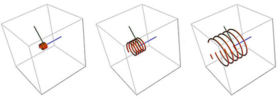
from zero to 1. In the comparative illustration below, the
particle's charge and the magnetic field are held constant and the
velocity of the particle as it enters the field increases from left
to right.
The faster the particle is moving, the
larger the radius of the resultant circular motion, because the
radius r is a measure of the particle's linear momentum mU where m
is the particle mass: r = mU ÷ (|Q|B).
The same result would apply if the
charge were to increase while the other two variables were held
constant.
If the charged particle enters the magnetic field at an oblique
angle, with a component of its motion vector in the direction of the
field, i.e., at an angle between zero and 90 degrees to the field
direction, it will "drift" in the direction parallel with the field,
while the field forces the particle into a circular motion. This
"drifting" circular path traces out a helix or spiral.
The "guiding center" of the circle
follows a field line of the magnetic field.
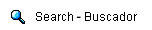
The radius r is known as the Larmor
radius or cyclotron radius. In the three illustrations below, the
angle of entry by the particle and the strength of the magnetic
field, B, remain the same, with a small drift motion toward the
right. The initial entry velocity is increased step-wise from left
to right, to show that the faster a charged particle enters a
magnetic field, the larger its radius of curvature.
In the series of images below, the green entry vector touching the
magnetic and electric field lines shows which way a positively
charged particle (by convention) is moving as it "enters" the
field(s).
The particle could be going in either
direction along this vector line at entry, so there are two
trajectories coming out of the tip of the green vector, as you will
see.
If the particle were charged negatively,
it would accelerate in the opposite direction, and if it were
heavier or moving faster, it would have a larger diameter circle
than depicted. Similarly, if the magnetic or electric fields were
changed, holding other factors constant, that would similarly change
the particle's behavior.
The narrow orange "tubes" represent the
particle's trajectory resulting from the entry conditions.
As a charged particle enters a uniform magnetic field B,
its path is
bent into a circle whose radius r is proportional to its linear
momentum, mass times velocity (mU).
The particle's speed does not
change, so its kinetic energy is unchanged,
and the field does no
work on the particle.
This is analogous to gravity's exerting a
continuous centripetal force on an orbiting satellite in space.
The magnetic field direction is shown by
a blue axial line; particle entry angle by a green radial line.
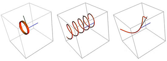
As the particle's entry angle into the B-field changes
from perpendicular to
parallel, its trajectory will change to a spiral.
The spiral will
decrease in radius as the angle decreases from 90 degrees
to the magnetic field
direction and approaches zero or parallel to the field.
Note the changing
angle of the green entry vector, left to right,
and the helical
stretching.
Images above created
with Mathematica Demonstrations
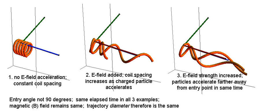
The total force will be the vector resultant of the electric and
magnetic forces and depends on the angle between the two fields.
If the electric and magnetic fields are parallel (as in the
field-aligned current situation we will consider later), then a
charged particle approaching radially to the axial direction of the
fields will be constrained to move in a helical path aligned with
the direction of the fields.
That is to say, the particle will
accelerate (constantly change its direction to spiral around the
axial direction of the magnetic field) as a result of the Lorentz
force, and will simultaneously accelerate (change its scalar speed)
in the direction of the electric field.
This makes successive revolutions
farther and farther apart as the particle's velocity component in
the E-field direction increases over time.
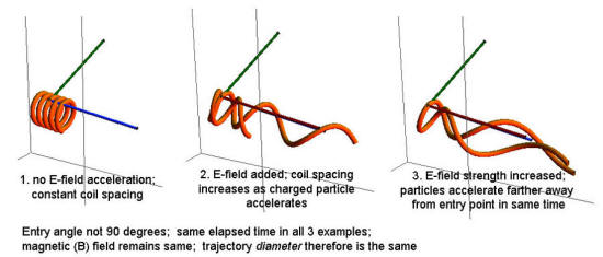
In this field-aligned situation (E and B fields parallel) a particle
trajectory
has the centripetal circularizing magnetic force applied
at
the same time that the E-field vector (red) forces it to
accelerate axially.
Over time the particle is moving nearly parallel
to the fields.
If the charged particle enters the combined, aligned field axially
(parallel to the magnetic field), it experiences no magnetic field,
so force to revolve around a guiding center is not exerted.
The electric field, however, will still
accelerate the particle along the field lines. Depending on its
charge, if the particle enters in the direction of the accelerating
force, its velocity increases. If it enters counter to this force,
it decelerates and may stop and accelerate back in the opposite
direction.
Recall that the "direction" of an
electric field is defined as the direction that its force is applied
to a positively-charged particle.
If the fields are not aligned, various trajectory combinations can
occur depending on the particulars of the charge, field strengths,
entry direction and angular misalignment of the magnetic and
electric fields.

With a constant electric field present, its general tendency will be
to accelerate particles ever more closely aligned with its field
lines,
and to increasing velocities.
Images above created with Mathematica Demonstrations
Although these trajectories may look complex, they involve only a
single charged particle at a time, with constant electric and
magnetic fields, with the same entry velocity. In practice many
charged particles of different polarities and velocity vectors may
occupy a volume of space at once, and their electric and magnetic
interactions will affect the field values in which they move.
There may also be neutral particles present, as well as dust and
grains and large bodies, all of which may exert other forces
(gravity, viscous, collisions) on the plasma interactions, too.
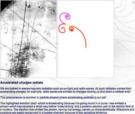
We note in passing that secondary effects of relativistic electrons
spiraling around magnetic field lines in space are often detected in
the form of synchrotron radiation.
From consideration of the Lorentz Force
Law, we know that there must therefore be an electric field aligned
with the magnetic field and that the axial movement of the spiraling
electrons with a velocity component parallel to the magnetic field
constitutes a field-aligned current.
These currents are Birkeland currents;
they occur at many cosmic scales.
4.4 Other Effects of the Field
Equations
It is worth remembering some basic results arising from the
application of the electromagnetic field equations.
-
Electric fields cause a force on
all charged particles.
-
The electric force will be in
opposite directions for oppositely charged particles;
therefore, an electric field will produce opposite
velocities of ions and electrons and so tend to separate
them. Charge separation in space is important in plasma
physics.
-
Magnetic fields only act on
moving charged particles having a component of motion
perpendicular to the magnetic field. Because the force
depends on the cross-product of the velocity and field
vectors, the effect will be different in different
directions. This results in a direction-dependent electrical
resistance. Think of trying to swim straight across a river
rather than with the water's current.
-
The direction of the magnetic
force is momentum and charge-dependent; ions and electrons
will therefore circle in opposite directions with different
radii and periods of rotation.
-
Bulk plasma moving across the
direction of a magnetic field will cause a local electric
field to develop which itself will cause new forces on the
charged particles.
-
Changes in the distribution of
charged particles cause a change in the electric field
between them; a changing electric field generates a change
in the magnetic field.
-
The Maxwell Equations and the
Lorentz Force Law act together as a feedback loop modifying
the motions of the charged particles and the fields in
complex ways.
4.5 Replacing Currents With Magnetic
Fields
The question arises as to whether electric currents can be replaced
by magnetic fields using Maxwell's Equations, which would make the
solutions much easier.
The answer is, technically, yes they can in certain simple
situations, and this is often done in magneto-hydrodynamic theories
and models because it is more convenient for studying certain plasma
phenomena. However, there are many aspects of plasma behavior where
it is necessary and crucial to consider the movement of the charged
particles because simply considering the field behavior cannot model
the observed complexity of plasma behavior.
The situation is analogous to the wave-particle duality in particle
physics: there are some situations where it is necessary to use the
particle description.
Examples of plasma behavior requiring use of the particle or current
description include cellularization and filamentation, energy
transport, and instabilities. Consideration of electric currents and
circuits also necessitates the use of a particle-based description.
Simply considering only the field effects in these situations will
miss the true complexity of plasma behavior.
We shall look at some of these more
complex behaviors next.
Back to Contents
Chapter 5 - Plasma Sheaths, Cells,
and Current-Free Double Layers
December 3, 2011

The Saturn
aurora's reddish color is characteristic of ionized hydrogen plasma.
Powered by the
Saturnian equivalent of (filamentary) Birkeland currents,
streams of charged
particles from the interplanetary medium and solar wind
interact with the
planet's magnetic field and funnel down to the polar regions.
Double layers are
associated with filamentary currents and current sheets,
and their electric
fields accelerate ions and electrons.
Image credits: Wiki
Commons; J.Trauger (JPL), NASA, Hubble Space Telescope
5.1 Plasma Temperature and Potential
We have seen that temperature is a measure of the thermal energy of
the particles in matter. More specifically, temperature is a measure
of the kinetic energy of the particles' random thermal motion.
An electron has only 1/1840th the mass (approximately) of a proton,
so electrons will have much higher velocities than ions at the same
temperature.
This is because kinetic energy is
proportional to the mass of the particle and the square of its
velocity, K.E. = 1/2 mv². Therefore, at the same temperature, the
ratio of velocities will be inversely proportional to the square
root of the particle masses.
For example, average electron velocity will be around 43 (i.e.,
√1840) times higher than the velocity of a single proton. If the
positive ions in the plasma are heavier than a single proton then
the difference will increase accordingly.
What is more, because of the Principle of Conservation of Momentum,
an electron will tend to undergo a larger change in its velocity
than an ion does in a collision between the two particles.
The electrons' higher velocity results in more rapid interactions,
which means that the electrons reach thermodynamic equilibrium ("the
same temperature") amongst themselves much faster than the ions do.
Any increase in velocity, whether from collisions or external energy
inputs, is therefore 'shared out' amongst the electrons very
rapidly.
For these reasons, it is common for the electron temperature in a
plasma to be different from the ion temperature.
Often the electron temperature will be
higher than the ion or the ambient temperatures. This is especially
common in weakly ionized plasmas, where the ions are often near the
ambient temperature while the faster-moving electrons have high
temperatures. Wikipedia reference on plasma temperature here.
In a plasma the temperature is often expressed as a thermal
potential which is equal to the potential drop (change in voltage)
through which the particles would have to fall in order to gain the
same amount of energy. The kinetic energy can then be expressed in
electron-volts or eV.
The hotter the plasma, the faster the electrons and ions are moving
in random thermal motion and the higher their potential. A potential
of 1 eV is equivalent to a temperature of 11,604.5 K.
Particles with potentials many orders of
magnitude higher are common in space.
Note:
one must be cautious about the
conversion between electron volts and thermal temperatures in
plasma.
Plasmas can become ordered so that
charged particles follow paths that are aligned with the local
direction of the accompanying magnetic field. Such current flows
are termed field-aligned currents.
Under this condition, charged
particles are moving approximately parallel to one another, and,
partly due to the low density of particles, collisions of the
thermal variety can become very rare.
The high temperature alleged for the
solar corona is based on spectroscopic observations of the light
(electromagnetic radiation including frequencies outside visible
light) which indicate how much ionization of atoms has occurred.
The ionization energy in eV is inferred
from the wavelengths of light emitted, and converted by the formula
above to equivalent temperature.
The thermal aspect of temperature which
is caused by large numbers of random collisions is not necessarily
present, however, even if there has been sufficient energy input to
strip electrons away from their nuclei. The electrons can be fast
(energetic) while their (thermal) collision rates are low.
The high velocity of the electrons is especially important in
understanding many aspects of plasma behavior, including radio
galaxies, galactic and stellar jets, and production of synchrotron
radiation and cosmic rays.
5.2 Development of Surface Sheaths
If plasma is contained within a laboratory tube or other vessel, the
electrons and ions in the plasma will impact the walls of the vessel
with a frequency proportional to their velocity. On impact,
particles are absorbed by the walls.
As the electrons have much higher velocities than the ions, the rate
of electron impact will be many times that of the ion impacts. As a
result, the walls of the vessel will acquire a negative charge.
As the negative charge on a surface develops, arriving electrons
will tend to be repelled from the surface. Only those electrons with
sufficient velocity to overcome the repulsion will still be able to
impact the surface. The negative charge on the surface will continue
to increase until the number of electrons hitting the surface equals
the number of positive ions arriving.
The plasma and the surface will have
achieved a balance, or steady state.
In the steady state, only the fastest electrons will still be able
to get through the adverse potential gradient from the negative
surface. Most electrons will be prevented from approaching the
surface. This results in a layer of plasma adjacent to the surface
in which the ions outnumber the electrons. This positive layer is
known as a Debye Sheath.
Similar effects are found if the surface is charged negatively or
positively by connecting a source of potential such as a battery.
The charge on the surface repels like charges in the plasma, leaving
behind an oppositely-charged sheath.
5.3 Extent of a Sheath
A surface sheath does not have a definite physical boundary but may
be considered to end where the potential resulting from the negative
surface and the positive sheath acting together balances the
potential of the plasma itself.
In other words, the sheath boundary is
where the potential is just sufficient to repel electrons with
energy equal to the plasma potential.
For example, if the plasma potential is +1V then the nominal
boundary will have a potential of -1V.
The explanation is as follows:
The boundary has a negative
potential because the sheath must repel approaching electrons.
The electrons in the plasma have a kinetic energy of 1eV.
Therefore, the sheath needs -1V potential to stop the
approaching electrons from reaching the surface.
This is analogous to rolling a ball up a
hill. If the ball has enough kinetic energy then it will reach the
top.
If not, it will get a part of the way up
before coming to a stop and then rolling down again. The sheath
potential is analogous to the height of the hill.
It can be seen that the sheath does not have a 'hard' edge and in
fact the potential field arising from the negative surface continues
past the sheath 'boundary'. Nevertheless, the boundary may be taken
as the point at which the negative surface is effectively
'neutralized' by the sheath because electrons with the plasma
potential are 'reflected' back into the plasma at that point.
American chemist and Nobel laureate Irving Langmuir developed
measurement methods and observations of plasma actions.
An interesting and useful PDF lecture,
'Plasma, Sheaths and Surfaces - The Discharge Science of Irving
Langmuir,' can be found here.
5.4 Charged Bodies in a Plasma
Similar sheaths will form around any charged body in a plasma where
the body has a different potential from the plasma itself.
The plasma effectively isolates the
foreign body by forming a sheath round it. The sheath will tend to
screen out the electrostatic field from the alien charge in the same
way that a sheath tends to isolate a negatively charged surface.
The body eventually may be neutralized
by opposite charges that it absorbs.
If the charged body can artificially be given a positive or negative
charge by connecting it to an external source such as a battery,
ions or electrons, depending on the charge, will be attracted to the
body and so a current will flow. By careful measurement of the
current for a range of voltages, it is possible to measure the
potential of the plasma itself.
One such device is named a Langmuir
Probe after Irving Langmuir, 1881-1957.
5.5 Cellularization in Plasma
Similar effects also occur between two adjacent regions of plasma
with different characteristics.
For example, the two regions may have
different temperatures, densities, or degrees of ionization. In this
situation, the different velocity distributions in the two regions
will set up a double sheath at the boundary whereby each region
effectively insulates itself from the other.
The double sheath will consist of adjacent thin layers of positive
and negative charge, separated by a relatively small distance. It is
one type of Double Layer.
Because no externally driven currents
are involved, sheaths between different plasma regions are known as
Current-Free Double Layers (CFDL). More on double layers in plasma
here.
Note especially the external links,
linked reference papers and publications at the bottom of this
article.
Double layers and sheaths are well-known
phenomena in plasma dynamics, described in textbooks and best
described in Wiki's discussion of the Vlasov-Poisson equation:
"In general the plasma distributions
near a double layer are necessarily strongly non-Maxwellian,
1 and therefore inaccessible to fluid models.
In
order to analyze double layers in full generality, the plasma
must be described using the particle distribution function,
which describes the number of particles of species α having
approximately the velocity v near the place x and time t"
1 - From Wikipedia, Physical
Applications of Maxwell-Boltzman Distributions: The
Maxwell–Boltzmann distribution applies to ideal gases close to
thermodynamic equilibrium with negligible quantum effects and at
non-relativistic speeds. It forms the basis of the kinetic theory of
gases, which explains many fundamental gas properties, including
pressure and diffusion.
Importance of the reference above: This is the reason that
conventional hydrodynamic and magnetohydrodynamic equations of fluid
flow are inadequate to a full and reasonably accurate mathematical
description of plasma dynamics.
Consequently the computational method
called particle-in-cell (PIC) simulation was developed for plasma
modeling in massively parallel computer systems in the 1980s.
Here is a Wikipedia article on PIC, and
here is a more technical paper on the subject.
5.6 Formation of a Current-Free Double
Layer (CFDL)
We have seen that CFDLs form between regions of plasma with
different characteristics. As an example, let us consider the effect
of a temperature difference (in electron volts, ref. 5.1 above).
This causes an electric field to build up, which will accelerate
electrons back to the hotter region.
A net flow of electrons to the cold
region will continue to build up the electric field until a balance
is achieved between the numbers of hotter electrons moving to the
cool region and the number of electrons being accelerated back to
the hot region by the electric field.
The thin regions near the boundary containing an excess of ions or
electrons constitute a Double Layer at the boundary which has an
electric field and associated potential drop across it.
The formation of sheaths at boundaries between different plasma
regions creates cells of plasma. This cellularization is a defining
characteristic of plasma behavior.
Gases do not behave in this fashion,
which is one reason why it is not possible to apply gas laws to
plasmas.
5.7 Similarity to Fluid Mechanics
At first sight, a Double Layer (DL) appears to be something like a
shock wave in fluid dynamics.
Indeed, a DL does share some
characteristics of a shock wave in that it separates regions of
differing characteristics and acts to accelerate the medium.
In the case of DLs, however, the acceleration occurs as a result of
the strong electric field set up between the oppositely charged
layers. As the force from the electric field depends on the charge
on the particle, ions and electrons are accelerated in opposite
directions. Neutral particles are not accelerated at all by the
electric field, but may be entrained through viscous or other
effects.
Note that the formation of Double Layers cannot be effectively
modeled by fluid analyses such as magneto-hydrodynamics (MHD)
because it is caused by and is dependent on motions of different
individual particles, not on the bulk motion of the plasma.
A good introduction to Plasma Physics from Wikipedia's
perspective can be found here, including properties, phenomena and
mathematical models.
While Wikipedia often has well-written
articles, like anything else it can sometimes be unreliable or
incomplete, or prone to biased editing, so always use care when
evaluating articles from Wiki, as well as other sources.
Back to Contents
Chapter 6 - Currents, Filaments and
Pinches
December 6, 2011

Planetary
nebulas often exhibit characteristic
bi-polar symmetries
with a centered plasma pinch,
polar jets, and an
equatorial torus.
Image courtesy NASA,
ESA and the Hubble Heritage Team
6.1 Thermal Motion and Current
It is important to distinguish between random thermal motion and
uniform linear motion in a plasma.
The latter is an electric current which
flows due to the presence of an electric field.
The random thermal motion is measured by the temperature of the
plasma, or by the temperatures of the ions and electrons separately
if their temperatures are different. This motion, being a motion of
charged particles, is also a form of current, but one which
oscillates about an average position, as opposed to moving in one
direction only.
Strictly speaking, temperature can only
be an accurate measure of the energy if the distribution of
velocities of individual particles is Maxwellian, that is, if the
distribution is equivalent to that which would result from elastic
collisions between the particles.
Uniform linear motion results from an electric field and represents
a drift current. All particles with the same sign charge (positive
or negative) move in the same direction under the influence of the
electric field.
That is, in a plasma, where there are
roughly equal numbers of positive and negative particles ("net
neutrality"), we find the positively charged particles moving
together in a direction opposite that of the electrons' motion.
The particles all have kinetic energy, which may be high, but they
do not have a temperature as a result of this linear motion.
That's because temperature is only used
to measure the energy of particles with random velocities,
undergoing collisions. As both types tend to move along more or less
aligned or parallel trajectories, and plasma densities are
relatively low, collisions are less common and Maxwellian collision
conditions are not obtained.
Both types of motion exist simultaneously wherever a current is
flowing. The current motion or drift of the particles is
superimposed on the random motions.
Another way of looking at this is to
think of the mean position of the random motion as moving with the
drift velocity in the direction of the current.
6.2 Electron and Ion Currents
We have seen that the electrons acquire much higher velocities than
ions due to their smaller mass.
However, an electron carries the same
magnitude of (negative) charge as a positively charged proton, the
lightest form of ion. Therefore, the higher velocity of the
electrons means that they are more effective than the ions at
carrying current in a plasma.
The ratio of the electron current to the ion current in a
non-relativistic plasma current is proportional to the square root
of the inverse ratio of the masses.
For the lightest positive ion, a proton,
this means that the electron current is around 43 times greater than
the ion current. [ If the mass of an electron is taken as 1, the
mass of a proton would be about 1836 times greater): √(1836 ÷ 1) =
42.85 ]
In many situations, it is the motion of
the electrons which determines the plasma behavior.
6.3 Current in Laboratory Discharge Tubes
Plasma has been studied in laboratory experiments for over a hundred
years, and a vast amount of experimental data and analysis is now
available.
One of the fundamental experiments
involves a Glow Discharge Tube in which a current is passed through
a low-pressure gas such as mercury vapor. This causes ionization of
the gas and creation of a plasma within the tube.
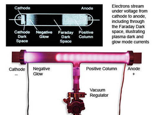
Evacuated (low
pressure gas) tube
with anode and
cathode and high-voltage power source.
Image credit: Wiki
Creative Commons
6.4 Glow Discharge Tubes
Many descriptions of discharge tubes are available and will not be
repeated here in detail.
The salient points for the present
purposes are as follows:
-
Within the tube, there are
visible bands along the axis wherein the plasma is seen to
glow, interspersed with 'dark' bands where there is no such
glow. The different bands represent two of the three
possible modes of operation of plasma when carrying a
current.
-
The dark bands represent,
unsurprisingly, the Dark Current Mode. In these regions the
electron velocity is below that necessary to cause visible
excitation of the atoms of neutral gas, although ionization
will start to occur at higher currents. However, radiation
will be given off at wavelengths outside the visible even in
the Dark Current Mode and so may be detected by non-optical
means.
-
The glowing bands represent the
Normal Glow Mode. Here, the velocity of the electrons causes
ionization to occur. The glow is caused by radiation from
the electrons of neutral atoms after they have been excited
by collisions with fast free electrons.
-
The third possible mode of
plasma operation is the Arc Mode, familiar in painfully
bright welding applications or lightning, for example.
-
Returning to the glow discharge
tube, one might expect that the potential difference between
the electrodes would cause a uniform electric field along
the length of the tube. However, the plasma behaves
differently.
-
It is found that a Double Layer
(DL) develops in the tube which modifies the externally
applied electric field between the anode and cathode. The DL
forms in such a way that the majority of the potential drop
occurs across the DL. Away from the DL region, much of the
remainder of the plasma is a glow discharge region known as
the positive column. This can extend for a significant part
of the length of the discharge tube.
-
Within the positive column there
are approximately equal numbers of electrons and ions. The
plasma here is therefore quasi-neutral. Because most of the
potential drop occurs across the DL, only a small but
constant voltage gradient, or electric field, exists within
the positive column.
-
There appear to be analogies
between the positive column in a discharge tube and the
plasma within the Sun's heliosphere. Another result of the
discharge tube experiments is also relevant to our
discussion of plasma behavior and will be discussed in the
next section.
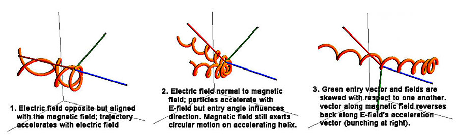
6.5 The Voltage-Current Density Curve
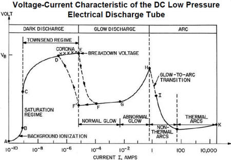
voltage-current curve
If the voltage V is plotted against the current density J in a
discharge tube (current density is the current divided by the area
of the discharge tube), then it is found that the three different
plasma glow modes correspond to three different sections of a
discontinuous graph, known as the voltage vs current or V-J curve.
In the dark discharge mode, the V-J curve rises with increasing
voltage, although not regularly. Once the voltage reaches a high
enough value, ionization begins and the current starts to rise very
rapidly for very little increase in voltage.
The discharge will then change rapidly into the glow discharge mode.
This is accompanied by a dramatic step change in the voltage. The
voltage drops right down because, when large numbers of electrons
have been produced by ionization, only a small voltage is needed in
order to generate a large current.
A very significant effect often occurs in the lower current density
part of the glow discharge region.
The voltage actually decreases with
increasing current density. In other words, the plasma finds it more
efficient to transmit the current at a higher current density
because the voltage drop is less.
At still higher current densities, the voltage increases again,
meaning that the glow discharge section of the V-J curve has a
minimum at a particular value of current density. This minimum
represents the point of lowest resistance for transmission of the
total current.
In cosmic plasmas, this effect may be
significant in causing the formation of current filaments by
confining the current within a particular cross-sectional area.
Similarly, in the extremely bright arc discharge mode, the voltage
once again decreases with increasing current density. If plasma is
forced into the arc mode, it will again tend to filament in order to
reduce the voltage drop.
6.6 Current Filamentation
Filamentation is observed to be a normal behavior mode for currents
in a plasma, as evidenced by the J-V curve and by physical
structures in space itself.
A paper by Dr. Anthony Peratt regarding
filamentation can be
found here.
In particular, current sheets (which we will consider later) tend to
break up into individual filaments due to the development of
vortices. These vortices are somewhat similar to those found in
fluid flows with adjacent layers of different flow velocities
(Kelvin-Helmholtz instabilities).
Clearly, the conditions inside a current filament are going to be
different to those in the rest of the plasma.
This causes a
current-free double layer (CFDL) to form at the boundary of the
filament in the normal way, such that the faster electrons are
confined to the filament by the electric field within the DL.
We can now see that filaments are current-carrying elongated plasma
cells with CFDLs at their boundaries.
Evidence of
filaments and electric currents in space is widespread.
Filamentary structure is acknowledged by most astronomers to exist
at all levels, from the solar system to galactic and intergalactic
scales.
The only area of disagreement between
the Electric Model and the Gravity Model is whether these filaments
are current-carrying structures, naturally following the laws of
plasma electrodynamics, or somehow fluid 'jets' thousands of
light-years long, gravitationally driven in accordance with computer
simulations of the hypothesized gravity forces due to cold dark
matter (CDM).
In a fluid, jets tend to dissipate rapidly into low-velocity plumes.
An aircraft's turbines expel jets of gas, seen here as contrails of
ice crystals precipitating some distance aft of the engines, which
quickly expand and decelerate to a stop in the upper atmosphere
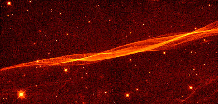
However, some jets in space, for example the 4,000 light-years-long
jet from the elliptical galaxy M87, appear to remain in the jet
state for enormous distances before dissipating into a plume.
This might indicate that the jets are
not fluid jets but electrical filaments.
The jet from galaxy M87.
Galaxy is the bright
knot, upper left, in visible light (reddish);
the jet extends down
and to the right, seen here in UV light (white and blue).
Image credit: NASA/
Hubble
A significant paper titled, "Measurement of the Current in a Kpc-Scaled
Jet" was published in 2011 in arXiv by Kronberg, Lovelace, et al,
based on their investigations of a jet emanating from radio galaxy
3C303.
If we assume they are electric filaments, then we need to know what
theory and experiment might tell us about how electric filaments
keep their shape over astronomical distances.
This is discussed next.
6.7 Current Pinches
Any current I flowing in a conductor or filament will cause a
magnetic field B around it. The lines of equal magnetic force will
be in the form of rings around the axis of the current.
The magnetic force will decrease with
radial distance from the axis.
From consideration of the Lorentz Force, it can be shown that the
interaction of the current I with its own magnetic field B will
cause a pressure radially inward on the current filament, written as
I × B (that is, "I cross B" in vector terminology).
This is called a 'pinch'
or 'z-pinch' (when defining the current flow as parallel
with the 'z' co-ordinate's direction).
In a metal conductor, the I × B pressure is resisted by the atomic
ion lattice. In a plasma current, the pressure can be balanced by
the pressure of the plasma inside the filament. This results in a
steady state where the current can flow axially across its own
azimuthal or circling magnetic field. The balancing equation is
known as the Bennett Pinch equation.
Lab demonstrations can use the pinch effect to crush aluminum cans
by applying a strong magnetic field very quickly. The can is crushed
before the pressure in the can is able to build up sufficiently to
resist the pinch force.
Magnetic field forces in lightning can
create an inward pinch that will crush a solid copper grounding rod.

Left: The
field generated by a fast 2 kj discharge through 3-turn heavy wire
crushed this can.
Right: Nature's
lightning z-pinch deformed this metal rod.
Images credit: Wiki
Creative Commons
6.8 Field-Aligned Currents
In space, the neutral gas pressure is usually negligible, and so the
balance between the I × B force and the pressure force cannot occur.
The only way the situation can be
resolved is for the I × B force to disappear. This implies that I
and B (current direction and magnetic field direction) are parallel
and, by vector algebra, the cross product is zero.
If other magnetic fields are present, as they are known to be
through much of cosmic space, then the I × B force must be
calculated using the total magnetic field, that is, by adding the
current's own B to the general B, added using vector algebra.
Thus in a space plasma, the current I and the total magnetic field B
realign so as to be parallel. In other words, the current follows
the magnetic field: it is a 'field-aligned' current.
Even if there is no external magnetic field, any small elements of
current flowing in a plasma will tend to accumulate naturally into
larger currents which generate their own magnetic fields and so
preserve the filament of current.
What happens is that electrons nearer the centre of the filament
flow in almost straight lines and generate an azimuthal magnetic
field around them. Electrons further from the centre are influenced
by this azimuthal component of the magnetic field and move in a more
helical path aligned with the main current direction.
This helical motion creates the
straighter magnetic field lines near the axis, as shown in the
following diagram. The nearer the centre of the filament, the
straighter are the magnetic field lines and the paths of the
electrons.
Electron flows in a magnetic-field-aligned current
varying with distance from center of filament
Wiki Commons
Any individual electron in the current is thus flowing along the
magnetic field direction in its own vicinity, but collectively the
filament is preserved even without an external magnetic field. This
means that very large currents can be assembled out of small current
elements and transmitted over huge distances.
Another way of looking at this is to consider the electrical
resistance of the plasma.
Current flowing across the magnetic
field direction will experience more resistance than current flowing
along the magnetic field direction because of the U × B term in the
Lorentz Force Law.
Effectively, the parallel resistance is
less than the perpendicular resistance, so the current tends to flow
in alignment with the magnetic field.
6.9 Self-Constriction of Currents
Detailed mathematical analysis shows that I and B interact in such a
way that both I and B tend to spiral parallel to each other around
an axis aligned with the external B.
The net effect is that I and B both
follow a helical path aligned with the direction of the external B
field.
It is also found that the interaction of the axial and azimuthal
(ring) components of the helical I and B cause both I and B to be
largely confined to a cylinder of definite radius centered on the
axis.
To summarize, the absence of significant pressure in space plasmas
causes currents to flow in cylindrical filaments aligned with the
general magnetic field direction. Within the cylindrical filament,
both the current and the magnetic field will spiral around the axis
of the cylinder whilst remaining parallel to each other.
Note that if for any reason the parallel alignment between I and the
total B is disturbed, then an I × B force will arise and cause
either radial compression or radial expansion, depending on which of
the two components is more axial.
Thus pinching of a filament could occur
because, for example, of changes in the fields through which the
current filament was flowing.
6.10 Stability of Current Filaments
Another significant factor emerges from the mathematical analysis.
The force-free or field-aligned
arrangement is a minimum energy state for the current to flow in.
This means that the field-aligned arrangement is inherently stable.
Unless disturbed by external factors, currents will tend to remain
aligned with the magnetic field.
We can now see how field-aligned currents can persist over vast
distances.
Field-aligned currents are therefore a
much more likely explanation of the collimated (parallel-flow)
'jets' seen to be extending for hundreds to thousands of light-years
than is the Gravity Model explanation based on conventional fluid
flows.
The confinement of field-aligned
filamentary currents to definite cylinders of current by
electromagnetic forces is also consistent with the falling
characteristic of the J-V curve seen in laboratory experiments in
discharge tubes.
If the plasma is in Glow Mode, which in
space plasmas may mean a glow in wavelengths outside the visible
range, then the radius of the current cylinder will be determined by
a combination of the effects of the electric and magnetic fields and
the shape of the current density-Voltage curve.
Read more about the filamentation
process in dense cosmic z-pinches
in this paper
by Russian physicists A.B Kukushkin and V.A.
Rantsev-Kartinov of the Kurchatov Institute, Moscow.
6.11 Condensation of Matter
A further effect related to the I × B
force can also be determined by analysis.
Suppose that the current I is caused by
an electric field E. Now consider the force arising from the
interaction of E and B. Remember that I tends to become aligned with
the total B due to the forces on the current itself.
Then the E causing the current will not
be entirely aligned with the total B, which is the vector sum of the
external magnetic field through which the current flows and the
azimuthal magnetic field generated by the current itself.
As with the I × B force, there is also
an E × B force, whenever E is not parallel to B.
This E × B force acts on charged
particles in the current cylinder and causes both ions and electrons
to move towards the centre of a filament. Plasmas often contain a
high proportion of charged dust grains, which will also be drawn
into the filament. Viscous drag between the charged particles and
neutral atoms will tend to draw the neutral atoms towards the
filament as well.
Therefore, current filaments in space will tend accumulate matter in
them as a result of the misalignment of the electric field causing
the current and the total magnetic field.
Remembering that pinches can occur if any misalignment of I and B
occurs, any matter that has been drawn into the filament will also
be compressed if a misalignment of I and B occurs. If the pinch
force is large enough, it can fragment the filament into discrete
spherical or toroidal plasmoids along the axis of the current. Any
matter in the pinch zone would then become compressed into the same
form.
Because the electromechanical forces are vastly stronger than
gravity, this mechanism offers a means by which diffuse matter can
be accumulated and compressed in a much more efficient way than
gravitational compression of diffuse clouds of fine dust particles.
Of course, once the matter has been sufficiently compressed and if
it is neutralized by recombination of ions and electrons, then the
electromagnetic forces may be reduced to the point that gravity
becomes significant and continues the compression started by the
electromagnetic forces.
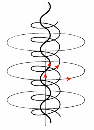
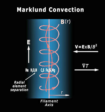
6.12 Marklund Convection
In the case of a cylindrical current, the E × B force is radially
inwards and results in the self-constriction of a current filament,
as we have seen. This results in an increase in the particle density
near the axis of the current.
Two things can then happen.
-
The first is that radiative
cooling from the regions of increased density can result in
a temperature decrease nearer the center, contrary to the
increase one might intuitively expect from increasing the
density.
-
The second is that recombination
of ions and electrons starts to occur.
Every chemical element has a particular
energy level, known as its ionization energy, at which it will
either ionize or recombine. This is analogous to the boiling point
of a liquid such as water: at a particular temperature, the phase or
state of the matter will change from one state to another.
If the kinetic energy of motion is equated with the ionization
energy, then a characteristic velocity, known as the Critical
Ionization Velocity (CIV), can be derived for each element.
Because temperature is a measure of
thermal energy, CIV can be related to temperature.
The CIV values of elements commonly
found in space are not distributed randomly but are grouped into
four distinct bands around certain velocity values. Within each
band, all the elements in that band have similar CIVs to each other.
In the vicinity of a field-aligned current, the E × B force causes a
radial drift of ions and electrons towards the cooler central axis.
Because of their differing CIVs, different ions will recombine at
different radii as they move towards the centre and enter
progressively cooler regions.
This process is known as
Marklund Convection after the
Swedish physicist who discovered it, Göran Marklund.
Marklund convection and sorting
in a
magnetically pinched current.
Image courtesy
of Wal Thornhill,
www.holoscience.com
The net result is that Marklund Convection sorts any elements
present in the locality into different groups according to their
ionization potentials. The groups of elements are arranged in
cylindrical shells at different radii within a cylindrical
field-aligned current.
As hydrogen has a high CIV compared to the other elements, it will
recombine first, in a cylindrical shell of larger radius than the
shells of the other elements.
This type of electrical sorting may be responsible for some of the
non-random distribution of elements that we observe in the cosmos.
In particular, it may explain the preponderance of neutral hydrogen
in thread-like structures throughout the galaxy that have been
detected by radio telescopes.
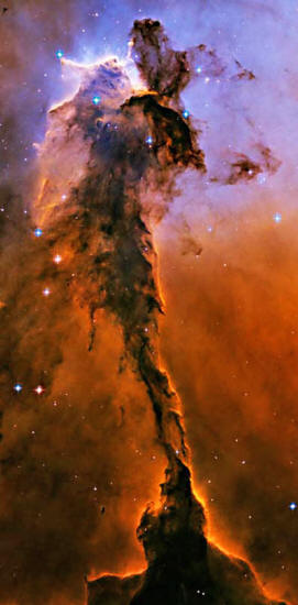
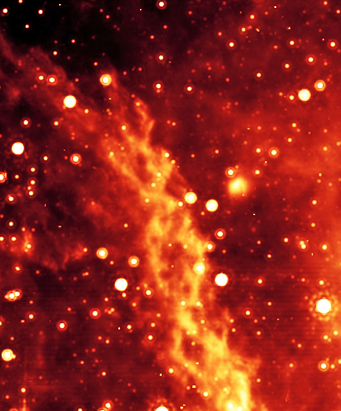
Could this Eagle Nebula image by the Hubble Space Telescope
be an
illustration of a cosmic magnetic pinch and resultant dusty plasma
surrounded by a hydrogen-helium environment?
Back to Contents
Chapter 7 - Birkeland Currents, Magnetic Ropes
and Current-Carrying Double Layers
January 4, 2012
7.1 Birkeland Currents
There is another
cause of filamentation of currents in plasma.
This is due to the
fact that there is a force of attraction between any two parallel
currents. Each current
generates a magnetic field which circles the first current
and attracts the
other current according to the normal laws of electro-magnetism.
Therefore the two
currents are drawn together.
This effect will apply to individual electron streams as well as to
wires carrying currents. Therefore, in a plasma, a diffuse current
will tend to become concentrated into a filament, as we have seen.
Similarly, a sheet of current will also
tend to coalesce into individual filaments, rather like a sheet of
falling water breaks up into individual streams.

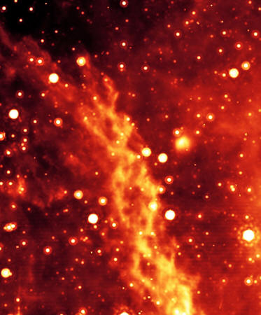
Braided current sheets glow softly in visible and infrared light
along the Cygnus Loop
of the Veil Nebula.
Image credit: W. P.
Blair, R. Sankrit
Johns Hopkins
University / NASA
If two parallel filaments occur in the same vicinity, or form out of
a sheet of current due to the filamentation processes, then they
will attract each other and initially move toward one another under
under the magnetic attraction described by the Biot-Savart Law.
Therefore there is a tendency for
current cylinders to occur in pairs.
The inverse-distance dependency of the Biot-Savart force law between
current-conducting filaments leads - curiously - to pairing of
filaments.
This shows 3 current filaments in a
particle-in-cell (PIC) computer simulation, where only two will
interact strongly while the third remains quiescent. This leads
directly to "twoness" or "doubleness" when many filaments are
present in a plasma with a significant magnetic field. Credit:
adapted from Fig. 3.21, Physics of the Plasma Universe, Peratt,
Springer Verlag,1992
A point of balance is reached when the long-range attraction force
is balanced by a shorter-range repulsion between the two
counter-parallel spiraling currents' azimuthal components.
Analysis shows that there is an offset
in the centers of the attractive forces that results in a couple, or
force of rotation, acting on each current.
The twin currents will therefore tend to
spiral around a common axis in a helical motion. As before, the axis
of the helix will tend to be aligned with the general magnetic
field.
This arrangement of current pairs is known as a Birkeland Current
after the Norwegian physicist Kristian Birkeland, who first studied
them in the early part of the 20th Century.
7.2 Magnetic Ropes
The spiraling effect of currents around each other gives the
appearance of twisted ropes.
Because the currents are aligned with
the magnetic field,
Birkeland Currents are often called
'magnetic ropes' or 'flux tubes'. Although not inaccurate, this
description tends to disguise the current-carrying nature of the
filaments and imply that the effect is due to magnetic forces alone.
As we have seen, this is not correct.
Birkeland currents can also attract matter from the surrounding
region.
This is because the azimuthal magnetic
fields created by each axial current form a pressure gradient
radially inwards with a minimum between the two currents, while the
magnetic fields extend beyond the current rope itself. This causes
charged matter and ionized species external to the current rope to
be attracted toward the centre of the current rope, the process
known as Marklund Convection (see 6.12).
Although the effect is similar to the I × B force of a single
current cylinder, the magnetic pressure minimum between the twin
currents can be a more efficient mechanism for concentration of
matter.
The plasma density outside the Birkeland Current is reduced while
the density inside the rope is increased. Birkeland Currents are
therefore often associated with density variations in the plasma.
7.3 Visible Effects of Currents in
Space
Twisted current
filaments
in the Double Helix
Nebula near the center of the Milky Way,
in infrared light.
Image credit:
NASA/JPL - CalTech/UCLA
Filamentary structures of the type just described are common in
space: examples include,
Filamentary neutral hydrogen structures
have already been mentioned (see Marklund Convection in 6.12 above).
Filamentary structure has also been
observed in the arrangement of clusters of galaxies.
7.4 Current-Carrying Double Layers
We have already seen that Double Layers can form in glow discharge
tubes in the laboratory.
Obviously these DLs permit the
transmission of current through them, as well as having the property
of accelerating ions and electrons in the strong electric field
within the DL.
To distinguish them from CFDLs they are
known as Current-Carrying Double Layers (CCDL).
A CCDL forms in a different way from a CFDL. It is usually triggered
by some form of instability or change in the current flow.
As an example of a change which causes a CCDL to form, consider what
happens when a current passes into a region where the plasma density
is lower. As the current is mainly carried by the lighter electrons
we can consider the situation relative to the ions in the first
instance.
If the electron current did not change then the lower density region
would rapidly acquire an excess of electrons due to the 'stream' of
incoming (electron) current. This would result in a potential
difference in the lower density region which would repel further
electrons and disrupt the current flow.
Remembering that current is proportional to the product of electron
density and velocity, the only way for the electron density to be
reduced to the appropriate level whilst the total current is
maintained is for the electron velocity to be increased.
The way this is achieved is by formation of a CCDL at the boundary
of the lower density region which accelerates the electrons into the
region. The strength of the DL will increase until it is just
sufficient to provide the electron velocity necessary to reduce
their density to match the lower ion density and maintain charge
neutrality.
Of course the ions are also affected by the DL but the overall
effect is similar to that just described.
Also, the faster electrons can cause
additional ionization which modifies the requirement for additional
velocity but a DL will still be necessary to provide the necessary
acceleration.
7.5 Flow Instabilities and CCDLs
CCDLs can also be formed as a result of flow instabilities in the
counter-streaming electrons and ions comprising the current.
Various types of instability can occur.
One example is the Buneman or two-stream
instability which occurs when the streaming velocity of the
electrons (basically the current density divided by the electron
density) exceeds the electron thermal velocity of the plasma. In
other words, the drift velocity due to the current is higher than
the random thermal velocity.
The actual mechanism of the Buneman instability is complicated.
However, in essence, the density of ions and electrons in a plasma
will always vary locally from absolute neutrality. The plasma then
self-adjusts to correct any imbalance.
These density variations occur at a
frequency dependent on the plasma temperature and the current
passing through it. If the current density is high enough then the
frequency of the density variations is too fast for the plasma to
adjust itself. The situation has become unstable.
This type of instability has been found to lead to the formation of
a CCDL. The variations in ion and electron densities cause local
electric fields to develop. These fields exchange energy with the
ions, which begin to oscillate with large amplitude and so amplify
the density variations. Areas of differing charge density set up
electric fields between them.
As the electric field increases due to these density variations, the
electron flow in the current is disrupted and some electrons become
'trapped', or start to flow backwards in local vortices. The result
is formation of a CCDL with populations of accelerated electrons and
ions, and trapped electrons and ions downstream of the DL.
This process is similar in some respects to fluid flow
instabilities.
The CCDL is in some ways like a
hydraulic jump, where the fluid velocities are different on either
side of the jump; the jump contains vortices of trapped fluid; and
the jump itself is 'fixed' in position.
However this is not to say that fluid analyses are complex enough to
model the electro-dynamical motions of charged particles in the
fields they themselves create. A principle difference is that the DL
accelerates particles, in opposite directions depending on their
charge, while a hydraulic jump reduces the fluid flow velocity by
introducing turbulence.
A CCDL will always concentrate a part of the current-producing
potential drop within the DL region and so reduce the potential
gradient in the remainder of the flow.
As CCDLs occur when changes in the flow characteristics occur,
pinches in the current, where the area of the flow is constricted,
may also cause DLs to form at the point where the flow area changes.
7.6 Energy Dissipation in DLs
Electrons accelerated across the potential drop of a CCDL will tend
to lose their energy in collisions with neutral atoms beyond the DL.
These excited atoms will in turn lose
energy by radiation as they return to the ground state. Formation of
a DL therefore acts as a means whereby the plasma can dissipate
excess energy in a manner analogous to a resistor in an electrical
circuit.
This mechanism contributes to the stability of plasma circuits by
'safely' dissipating the energy which might otherwise result in more
turbulent instabilities developing.
7.7 Classification of DLs
As already discussed, there is a principal difference between
current-carrying double layers (CCDL) and current-free double layers
(CFDL), which are formed by different mechanisms and distinguished
by whether or not the DL allows a significant electric current to
pass across it.
Another classification is based on the strength of the DL. Depending
on the potential drop across it, a DL may be classified as weak,
strong or relativistic. Each class will have different effects on
charged particles in the surrounding plasma.
If the potential drop across the DL is larger than the plasma
potential, then the DL is classified as a strong DL. A strong DL
will reflect particles that approach the DL with energies less than
the plasma potential. Only those particles with energies above the
plasma potential will enter the DL and be accelerated.
A weak DL will decelerate particles with the plasma potential that
approach from the 'wrong' side, but then re-accelerate them as they
pass through the DL.
If the potential drop across the DL is sufficient to cause particles
to acquire energy larger than the rest mass energy of the electron
then it is known as a relativistic DL.
A relativistic DL will
therefore accelerate electrons to near the speed of light as they
pass through the potential drop.
Back to Contents
|