|
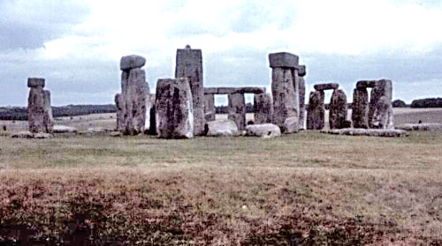
This original Stonehenge stands on a hillside about 8 miles north of the town of Salisbury. It was begun, archaeologists now believe, as a simple device by which the seasons could be foretold, using the position of the moon, relative to four stones and a ditch.
This had become necessary at that time since the local tribes had changed from hunting to farming as a way of providing food and needed a means of telling when they should plant their crops.
Figure 1. The
"original" Stonehenge on Salisbury Plain, England.
There is, however, some variation in the path of the moon over the sky, from year to year, so that this first attempt at a calendar was not very accurate.
Additional stones were
added over the centuries to form complete circles, around a central
altar stone, as the leading shaman or priest-equivalent (this was
long before the Druids) tried to make a more accurate calendar. It
was not, however, until the site was changed from marking the
position of the moon to that of the sun that the "calendar" finally
became accurate enough to pinpoint exact dates.
The outer of the two rings comprises 30 upright stones which stood
15 ft high was capped by a set of lintels notched to fit on the
uprights and arranged to form a continuous walkway around the top of
the stones.
Less prominent, but more necessary to tell the time between the major days when the sun shone in alignment with the great stones, a smaller bluestone ring of single stones was erected. There were 19 of these and it is likely no coincidence that 19 multiplied by 19 equals 361 which, if one adds 4 days for fasting, celebration and recovery to mark the end of the year, gives us a calendar.
There is a reference in some of the ancient Gaelic legends to days "when time stands still." (The Bahai faith has also, quite independently, developed such a calendar.)
An
alternative explanation has been proposed by Gerald Hawkins, who
suggests that these nineteen stones are related to the 18.61 year
cycle during which the moon-rise position will oscillate along the
local horizon.
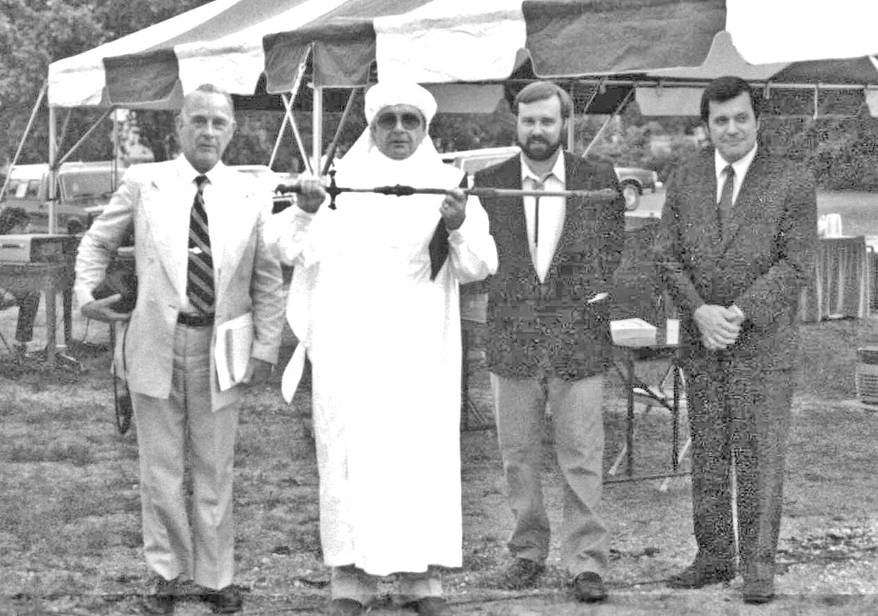
This interest, and the unique combination of expertise at Rolla, especially that of Dr Joseph Senne, then Chairman of Civil Engineering and a local astronomer, and the UMR high pressure waterjet group, led him to propose construction of the project to the alumni, who funded it.
Figure 2. (From the left) Dr Senne, Mr Bevan, Dr Carlson and Chancellor Marchello.
This happened partially because, in 1978, the National
Science Foundation funded a study to find better ways of quarrying
granite in the United States. One of the ways that were tested was
through the use of high pressure waterjets and Dr. Summers of the
UMR RMERC was one of the panelists who worked on that program.
Cutting rates of almost 24 sq.ft/hour were achieved in the overlying "sap" stone, and a slot was cut some 18 ft long and 42 inches deep. In the solid higher quality stone cutting rates were around 12 - 15 sq.ft/hour.
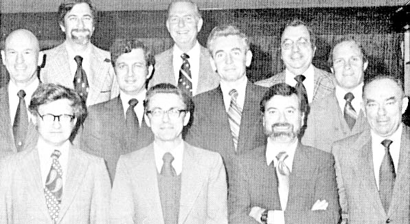
Figure 3. Original NSF panel: Dr. Summers (UMR) Mr. Tessner (Ga Tech) Mr. Stengel (Northwest Granite) Mr. Ralph (Barre, VT); 2nd row Mr. Tyler (Century Granite) Dr. Hakala (NSF); Mr. McGarity (Harmony Blue) Mr. Harper (Apex Granite) 3rd row Mr. Wright (Ga Tech) Mr. Coggins (Coggins Granite)
Mr. Kelly (EGA)
Although we received considerable help
from the Missouri Department of Natural Resources, we were unable to
find an alternative site from which we could economically have
obtained the rock.
Figure 4. Wedges
driven along the bedding of a block to split it.
The original Stonehenge is made of varieties of sandstone rock.
This rock has a clear bedding plane to it, so that it can be relatively easily split to form flat surfaces. Mining in Britain had been going on for at least a thousand years before Stonehenge was built, so that skilled miners would know how, using round stone hammers (still remaining at the site) flint chisels and deer antlers, to shape the stone.
Final carving to shape
was probably done by manually chipping the rock, after the rocks had
been moved into their final position. We surmise this from the
evidence of tools which were found at the site.
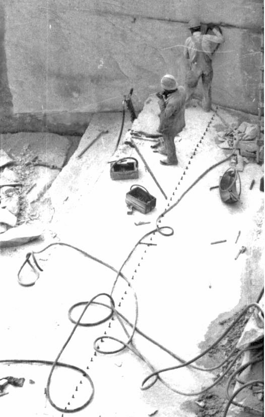
They are very noisy and are now being replaced in quarries by diamond impregnated wire cutting saws.
Figure 5. Slot being
cut into the solid rock with a thermal lance.
In modern quarrying the rock is broken out from the solid in large blocks which are then split into smaller pieces by line drilling.
At the time that the rock was quarried for
our Stonehenge, however, this practice was not common, and the rock
which we received was not cut into the more regular shapes which are
now produced from most quarries.
This creates a very narrow cut (which increases the amount of quality granite produced) and leaves a very smooth surface which can be used as one of the edges of the stone, whereas with the earlier methods the edge had later to be removed. (The latest method will be discussed later).
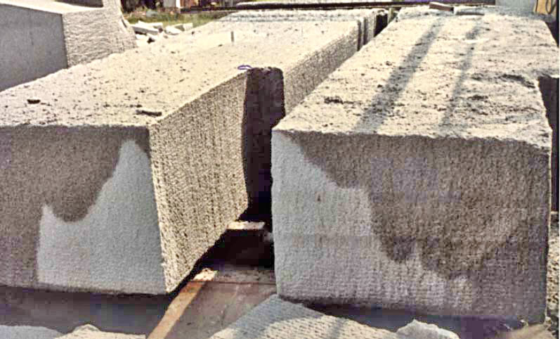
Those earlier methods left the rock which we received in Rolla in a ragged shape.
Figure 6. Typical
shape of the rock blocks as received at Rolla.
Once the rock was brought to Rolla a then novel method of mining, pioneered at UMR, was used to cut the rock.
Water was pressurized to 15,000 psi (7.5 tons to the square inch) and forced through a cutting lance fitted with two small holes, each about 0.04 inches wide (about the size of the wire in a paperclip).
Figure 7. Cutting
nozzle, showing the jets at low pressure.
These jets are spun, at a speed of 180 rpm and the whole cutting assembly moves over the rock at a speed of 10 ft/min.
As the jets hit the rock, they cut a slot between a quarter and a half inch deep and two inches wide. The cutting lance is then lowered this amount, and moved back over the slot. A frame was erected at the Rock Mechanics and Explosives Research Center to cut the rock.
It was assembled from wooden ties and radio antenna mast sections and provided a base along which the cutting lance was moved. A wire mesh screen was fitted around the frame to protect the operator from the small pieces of flying rock which were removed by the jets during the cutting process.
The cutting lance was pulled along the frame using a bicycle chain, and two small hydraulic motors were used, one to turn the nozzle assembly, and the other to draw it along the rock surface.
During the course of the rock cutting the jets were able to cut an average of sixteen square feet of rock an hour. The generator used to power the entire operation used between four and six gallons of fuel an hour.
Figure 8. Cutting
Frame used to carve the individual rocks.
In this way a relatively straight cut can be made on the rock surface without further damage to the rock. You can see the lines left by individual passes of the jets on some of the rocks.
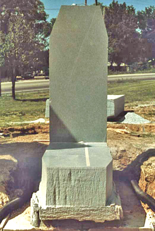
Figure 9. Carved
blocks for the North trilithon legs.
The base of the analemma stone was left partially uncut so that future generations could see how it was done (although it is buried under the current ground level). The lower analemma stone sits on a concrete pad and has two slots in its base, so that it can be re-leveled if necessary.
The organizing committee felt that this was an important consideration, when it is recognized that Missouri contains a fault at New Madrid which caused one of the largest earthquakes in recorded American history.
It will be easier to re-align the smaller analemma blocks, rather than the trilithons, after the next such earthquake.
Figure 10. Detail of
the lower analemma stone, before it was covered by soil.
UMR-Stonehenge is the first major
structure to be carved using high pressure waterjets, it marks the
transition from mechanical excavation of rock to hydraulic
excavation and thus is a major mining milestone.
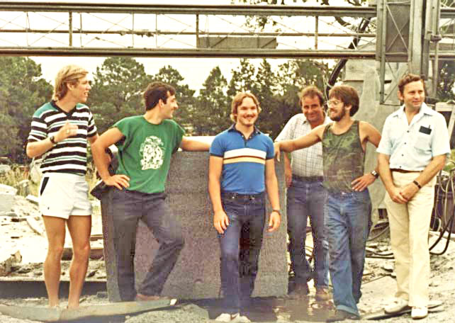
The rock was moved around during the cutting process using a crane.
Figure 11. The final group of students who completed the rock cutting
(Dr. Mazurkiewicz
is at the right and Mr. Gabriele who provided the crane service is
at the back).
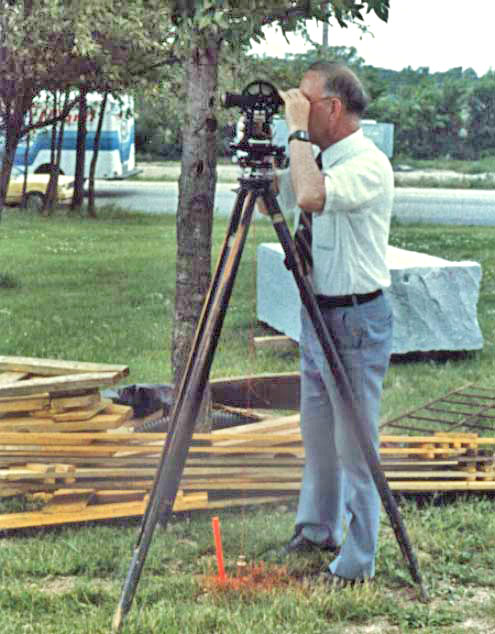
Figure 12. Dr Senne
checking the alignment of the Trilithons.
The rocks for the original Stonehenge were brought anywhere from 20 to 200 miles to the site.
Contrary to
popular myth, it is unlikely that vast teams of men hauled the rocks
all the way. While it would take some 700 men to pull one rock a
mile a day, oxen of that period could pull between 1,200 and 4,000
lbs each a distance of 20 miles a day, so that a span of 15 to 50
animals could have made the transport much easier and quicker.
By sharpening the bottom of the stones a little, it was then
possible to "walk" them into their final position. Final carving to
exact shape was completed after the stones had been erected.
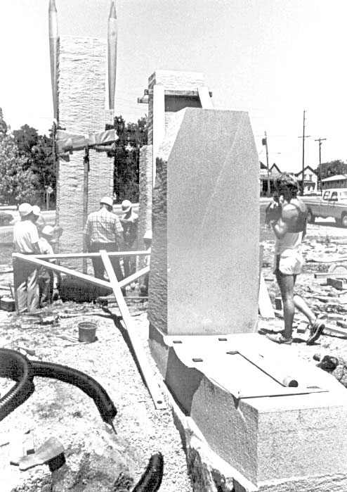
Figure 13. Using a
crane and straps to position one of the Trilithons.
It took over four hours to get each rock accurately aligned.
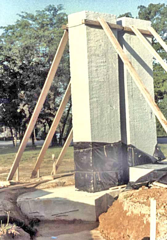
The great trilithon ring is set on an 18 in. thick concrete pad and each rock was set on this. Straps were tied around the center of each stone to lower them into place, and they were then held in position using wooden braces until they could be accurately aligned and set in the concrete.
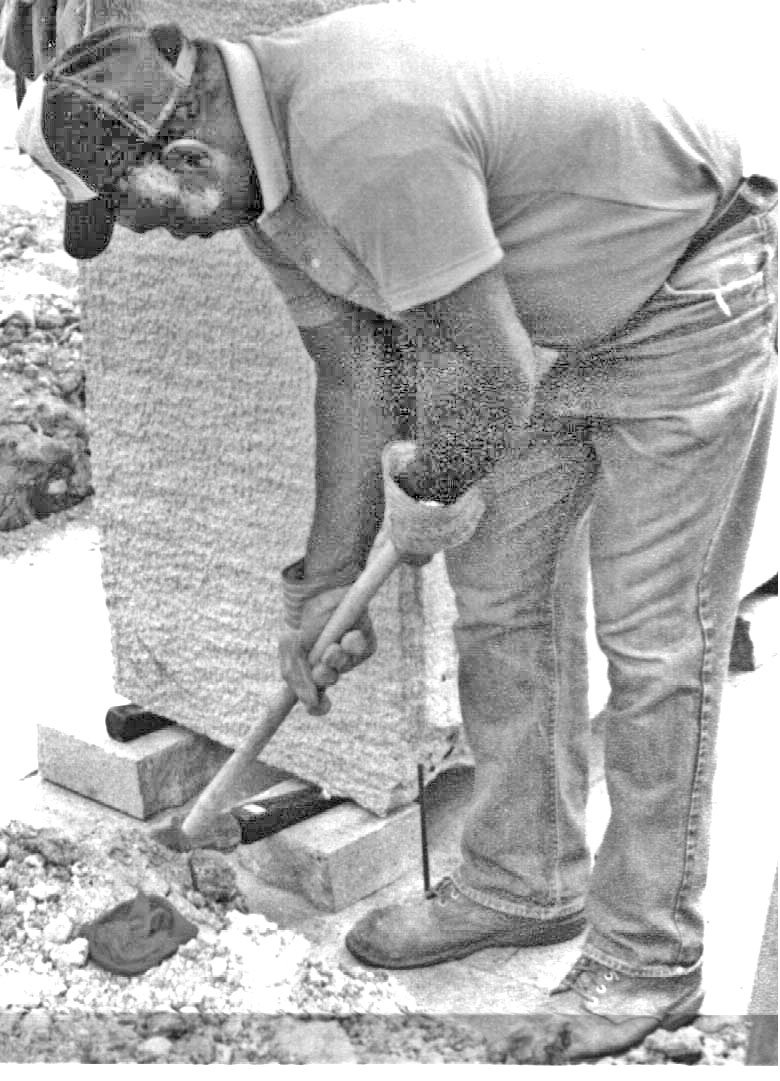
Wedges were then driven under the smaller stones (shims had to be set under the larger ones after lifting it with the crane) until they were level.
Figure 14. Adjusting
the block alignment with a wedge.
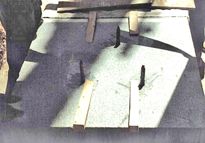
For the analemma stones where accuracy is critical, the rock angle was first measured, (it was 89.5 deg) and to ensure accuracy, 3 pins were set between the two rocks, while a shim 1/16 in. thick was placed under the back of the upright stone.
The upright was set the first time it was placed. The gap between the stones was then sealed with resin.
Figure 15. The three
pins used to align the anelemma stones.
Each rock was aligned by Dr. Senne who used the UMR computer to accurately identify the position of the stones.
Each stone was set, in turn, on the 18 inch thick concrete slab, which runs underneath the entire assembly of the five main trilithons.
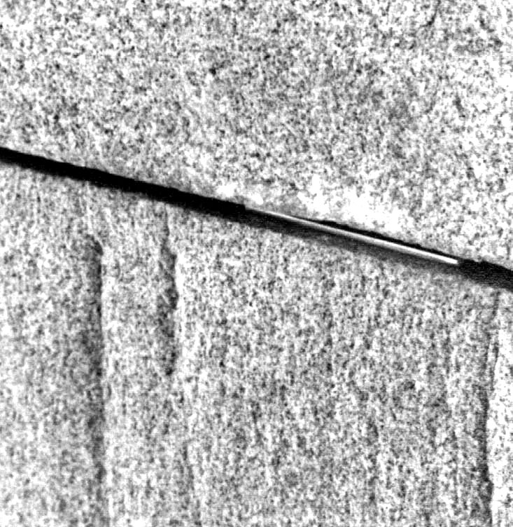
Figure 16. The small brass wedge used to align the analemma.
Another 18 inches of concrete was then
poured around each stone to hold it in place, and a wooden
scaffolding was used to hold the rock in place until the concrete
set. |