|
Standing Electrical
Waves Demonstration
Standing waves commonly occur on antennas and electric transmission
lines but are not visible. To visualize them, we need to build a
special piece of equipment called a set of Lecher transmission lines
and connect it to a radio transmitter. Fortunately, it's not too
hard to do. For example, the Lecher lines will be constructed out of
two pieces of ordinary copper tubing. The radio transmitter is the
most expensive part but a used one can usually be obtained for about
$100.
Once the apparatus is finished we will be able to see the standing
waves by placing an ordinary florescent tube between the two
transmission lines. The tube will glow brightly at antinodes and
dimly at nodes.
Background
We will be using the radio transmitter to produce an electric field
between the two transmission lines (copper tubes), so let's start by
understanding the nature of these electric fields or e-fields.
Electric field strength indicates the force that would exist on a
unit of positive charge if it were located at the point where the
electric field is measured. If the charged particle is negative the
force on it is reversed. Electric fields cause currents to flow and
are a very important part of electromagnetic radiation (a fancy way
of saying light which includes the types we see as well as those we
don't).
E-field strength at a location inside the florescent tube determines
if the electrons in the tube's contents are excited enough to jumper
to higher energy state. When they do, they invariably fall back to
their normal state and in the process emit a photon of light. This
is what makes the tube glow.
E-fields are vectors and can be represented on vector diagrams in
which the length of the arrow represents the e-field's magnitude and
the arrowhead the direction. Often e-fields are shown using ray
diagrams. The arrowheads on the rays point in the field's direction
and the spacing between rays represents the magnitude.
We are going to create a fairly complex standing wave on each
transmission line (t-line) so that points directly opposite each
other will have opposite charges. Since that's a lot to grasp, let's
start by visualizing a simpler case in which the top wire is
positive and the bottom wire negative (see Figure 1).
From Figure 1 we see that even this case is not so simple. The blue
lines represent the e-field emanating from the top t-line which is
positively charged. The red lines represent the e-field emanating
from the bottom t-line which is negatively charged.
The dashed lines represent the field above a given t-line and the
solid lines below. For example, a blue dashed line represents the
e-field above the top positively charge t-line.
Note that we are assuming that the wires
are very long and are ignoring non-linear fields at the ends.
Figure 1. Ray diagram
of an E-field
Generated by Two
Parallel Transmission Lines with Opposite Charges
Notice that the red and blue e-field
rays go in the same direction between the two t-lines. In other
words they reinforce each other. The red and blue e-field rays go in
opposite directions when they are above or below the pair of
t-lines. In other words, they tend to reduce e-field strength.
Hence, the e-field is mostly confined to the space between the two
t-lines. This will be true even when we eventually apply an AC
signal to the t-lines.
In order to insure that a point on one t-line is the opposite sign
from a point on the other t-line directly opposite, a small
transformer will be connected between the radio transmitter and the
t-lines. (These are available from Radio Shack for about $3.)
The small transformer also helps keep
the radio signal from being broadcast by the wiring between the
transmitter and t-lines due to impedance mismatch.
Figure 2. Modified
E-field Vector Diagram
Showing the Standing
Waves on a Pair of Transmission Lines.
Figure 2 shows a snapshot of the standing waves the radio
transmitter will create in the t-lines. Note that this is a modified
vector diagram. In other words the length of the arrows indicates
the magnitude of the e-field. The pattern of standing waves will
create places between the t-lines where the e-field is always zero
(called nodes) and other locations where the e-field reaches maximum
values (called antinodes).
The red and blue areas will tend to flip-flop over time which is why
we refer to Figure 2 as a snapshot. In other words. the bulbous
looking parts of the standing waves will alternate between positive
and negative e-fields. When a florescent tube is placed between the
t-lines, it will glow brightly in these areas. It will glow dimly,
if at all, where nodes are located.
The distance between nodes is equal to 1/2 the wavelength of the
standing wave. The velocity of the wave on the copper tubes will be
the speed of light (3.0 x 10⁸ m/s).
The relationship between wavelength,
wave speed and transmission frequency is as follows:
v = λ f
where:
v = wave velocity
λ = wavelength
f = frequency
For example, a transmission frequency of
400 Hz will give a wavelength of 0.86 meters (30 inches). This would
give a spacing of 0.43 meters (15 inches) between nodes.
Procedure/Operating Instructions
After building and assembling the equipment (see "building the
equipment" below) you will be ready to use it but first read the
cautions listed below. In theory, the t-lines will emitted virtually
no radio waves to the outside world. In reality some level of
radiation is usually emitted. This can interfere with other radio
transmissions. By paying attention to the cautions listed below the
potential for problems can be minimized.
Cautions
Radio frequency power can cause burns. It's best to limit radio
transmitter power output to no more than 5 watts and avoid holding
fingers or other body parts between the transmission lines.
Even when correct assembled and used, the equipment can create noise
in nearby radio transmissions. Be sure to follow the assembly
instructions. Keep power levels low and transmission times short. Do
not allow students to play with the equipment. Listen to the radio's
receiver before transmitting a signal to the transmission lines. Do
not transmit if someone is using the frequency.
|
Cautions |
-
Radio frequency
power can cause burns.
It's best to limit radio transmitter power output to
no more than 5 watts and avoid holding fingers or
other body parts between the transmission lines.
-
Even when
correct assembled and used, the equipment can create
noise in nearby radio transmissions.
Be sure to follow the assembly instructions. Keep
power levels low and transmission times short. Do
not allow students to play with the equipment.
Listen to the radio's receiver before transmitting a
signal to the transmission lines. Do not transmit if
someone is using the frequency.
|
Place a two foot long plastic florescent
fixture between the copper tubes (a four foot plastic fixture will
also work but is harder to find). The florescent fixture has to be
made of plastic since metal may interfere with the e-field.
Florescent grow lights can be used and are generally available in
plastic fixtures which are about the same size as a bare florescent
tube. The florescent light will be your standing wave detector.
Turn on the florescent light and radio transmitter. Press the
transmit button on the radio and hold it down. The tube may brighten
slightly when the transmitter goes on. Turn the power off to the
florescent tube and continue holding down the transmit button on the
radio. The florescent tube should continue glowing.
Move the florescent tube lengthwise between the copper tubes until
you locate a node. This will appear as a dark spot in the florescent
tube. Notice that the node remains stationary with respect to the
copper tubes even when the florescent tube is moved.
Generally, the florescent tube must be turned on before applying the
radio signal or the tube will not light. However, once material in
the tube is ionized it requires less than a watt of power to keep it
glowing. The florescent tube can be lighted using only a radio
transmitter but it can easily take over twenty watts of power to do
so.
A typical handheld transmitter will
provide 5 watts at most.
Alternative Demonstrations
The same procedure used to light a florescent tube between the
Lecher lines can be used to make a florescent tube glow using only a
handheld radio. Once again the tube is turned on and the antenna of
the radio held next to it. The transmit button on the radio is
pressed and the tube's power turned off. The tube will continue to
glow in the area around the antenna even after the power is shut
off. When the radio is moved next to the tube the glow moves with it
as long as the transmit button is held down.
We have tried this demo with both a cell phone and a wireless phone
without success. At this point it's unclear whether the reason is
low power, incorrect frequency, or some other problem.
The advantage of using the Lecher line set instead of the handheld
radio's antenna is two fold. First, the handheld antenna will
usually not be long enough to display multiple nodes. Second, the
Lecher wire set is less likely to interfere with outside radio
transmissions.
Troubleshooting Guide
If the florescent tube glows brightly and shows no nodes after the
power to the tube is turned off then the radio transmitter may be
putting out too much power. This is usually an easy problem to solve
even if your transmitter has no adjustment for reducing power. Start
by making sure a 6 Db attenuator (see Table 2) is attached to the
matching transformer.
This will cut signal power by a factor
of four. A second attenuator can be used if needed. Attach it in
series with the first. If that doesn't work, try lowering the
florescent tube below the two copper tubes. This will reduce the
strength of the e-field.
If the frequency of the transmitter is too low the wavelength will
be too long and the distance between nodes too large to see. If the
frequency is too high the anti-nodes will run together and the tube
will appear uniformly bright.
Table 4 gives data for the possible frequencies to use with various
lengths of copper tubing. Two frequency ranges are suggested based
on radio availability. These should be used with either 4 or 8 foot
long lengths of copper tubing in order to observe at least two nodes
which can be used for measuring wavelength. Make sure that your
radio's frequency is in the correct range for the tube length you
have used.
If the florescent tube fails to stay lit when the power is removed
then check all connections and make sure the radio has a fresh
battery if it uses one. To insure your radio is working, try
transmitting to a second radio if you have one. . Sometimes it's
possible to light the tube by tilting it. This puts a smaller cross
section of florescent tube between the copper tubes and sometimes
seems to help. Try removing the 6 Db attenuator (see Table 2). If
the tube still fails to light then the transmitter power is probably
just not high enough.
A four foot florescent tube can be used but it's harder to light.
It's also harder to find one with a plastic fixture. Metal fixtures
are not a good idea since they can interfere with the electric field
around the copper tubes.
Building the Equipment
First we need to build a short segment of a transmission line as
shown in Figure 1. We'll use two pieces of 3/4 inch diameter 8 foot
long copper tubing for the transmission lines and spacers built from
pine 2x4's. (Note: 2x4's are commonly used in house construction and
usually have to be purchased in 8 foot lengths.) Each spacer set
will be held together with a single nylon bolt with a wing nut. (The
bolt and wing nut are not shown in Figure 1)
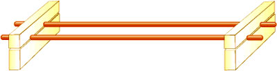
Figure 1.
Transmission Line Assembly
Cut a 3"x 6" block of wood out of a 2x4
and then drill the 7/8 inch holes for the copper tubing as shown.
Note: 3/4 inch is the inside diameter of the copper tubing. The
outside diameter is 7/8 inch. Do not drill 3/4 inch hole in the
board. Cut the block into two pieces on a table saw as shown. Be
sure to do this after the holes are drilled. This make it possible
to tighten the wing nut on the nylon bolt so that the spacer holds
the tubes firmly in position.
Generally it's a good idea to make three sets of spacers. If you are
using a well made drill press it's often a good idea to clamp the
blocks together and drill the tube holes simultaneously through all
of the blocks. This helps keep them aligned.
Shorten the 10 foot long 3/4 inch copper tube to 8 feet in length.
This makes them much more manageable in the classroom.
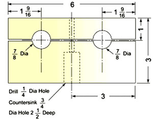
Figure 2. Spacer
dimensions.
(Note: the spacer is
cut from a pine 2x4 and is 1.5 inches thick.)
Drill holes in the center of two 3/4
inch copper tubing end caps so that a 1/2 inch long #8 sheet metal
screw can be screwed firmly into them. For the moment, however do
not put screws in the holes. Solder the drilled end caps to one end
of each piece of the copper tubing.
Solder two unmodified tubing caps to the
opposite ends of the two 8 foot long tubes. Make sure that you clean
all the surfaces to be soldered with steel wool and flux them with
rosin. These surfaces must make good electrical contact or the
demonstration will not work. The soldering can be done with a
propane torch.
Now you can insert the screws. They will be used as connecting
terminals. If they are inserted before soldering, the screws can
become soldered to the copper.
Assemble the three wooden spacers to the tubes. These can be
positioned at any position along the tubes and moved to various
locations as needed.
Attach one of the spade connectors on the matching transformer (
RadioShack part number 15-1230) to the end of each copper tube.
Screw on the coaxial to BNC adapter and attach one end of the four
foot long cable to the adapter and the other to the radio
transmitter. The connecting cable must be 50 Ohm coaxial cable or
there will be a mismatch of impedances between the radio and the
cable. This reduces efficiency by reflecting part of the signal back
into the radio.
Do not attempt to connect the radio directly to the copper tubes
without using the matching transformer. This will cause a mismatch
in impedance between the cable and the copper tubes which turns the
connecting cable into a transmitting antenna. This can cause
unwanted noise in local radio transmissions. The whole idea behind
the Lecher transmission lines is to confine the e-field between the
transmission lines. This prevents the transmission of signals to the
outside world.
Once all the equipment is assembled you are ready to test it. See
above for operating instructions.
|
Table 1. Materials for
Building the Lecher Wire Set |
|
Num. |
Quantity |
Price |
Item |
Total |
Comments |
|
2 |
each |
$5.60 |
10 ft long straight pieces
of 3/4 inch copper tubing. |
$11.20 |
These will be shortened to 8
ft. If you decide to build a 4 ft set of t-lines buy a
single 10 ft long piece of tubing. Be sure to check the
tubes for straightness. |
|
4 |
each |
0.30 |
3/4 inch copper tubing end
caps |
1.20 |
|
|
1 |
each |
3.00 |
a 20 inch long piece of pine
2 x 4 (note that the price is for an 8 foot long 2 x 4
board) |
3.00 |
Normally an 8 foot long 2 x
6 is the shortest length which can be purchased. The
project will only use 18 inches. Spend a little extra
and get the highest quality wood you can find. It will
give better results with very little extra cost. |
|
3 |
each |
0.60 |
1/4 inch dia x 2 inch long
nylon bolt with washer and wing nut |
1.80 |
These need to be nylon to
eliminate possible interaction with the electric field
which will be generated between the two copper tubes. |
|
Pre-Tax Total
|
$17.20 |
Cost is approximate and will
vary from location to location. |
|
Table 2. Electrical
Materials Required to Operate the Lecher Wire Set |
|
Num |
Quantity |
Price |
Item |
Total |
Comments |
|
1 |
each |
$4.00 |
300 Ohm to 75 Ohm Matching
Transformer part # 15-1230. (RadioShack) |
$4.00 |
This is an essential item
which prevents the connecting wire from acting like an
antenna. |
|
1 |
each |
1.70 |
Female BNC to Coaxial
Adapter (RadioShack) |
1.70 |
|
|
1 |
each |
3.50 |
6 Db, TV/VCR Signal Overload
Attenuator part number 15-1257A. (RadioShack) |
3.50 |
|
|
1 |
each |
6.00 |
3 foot long coax RG-58 (BNC
to BNC) patch cable. (RadioShack) |
6.00 |
typical coax cables are 75
or 50 ohm impedance. 50 ohm (as specified at left) is
needed to connect to handheld radios. |
|
1 |
each |
|
Handheld radio transmitter ,
4-5 watt maximum output. Generally outputs of as little
as one watt will work. |
100 Used 250 new |
Usually handheld battery
operated units work well. |
|
1 |
each |
8.00 |
2 Foot Long Single Tube
Plastic Florescent Fixture With Tube. (Walmart) |
8.00 |
Grow lights or standard
florescent tubes work well. A larger tube will show more
nodes but is harder to find with a thin plastic housing |
|
Pre-Tax Total without radio
or Lecher Wire Set |
$23.20 |
Cost is approximate and will
vary from location to location. |
|
Pre-Tax Total with Lecher
Wire Set but not radio |
$40.40 |
Cost is approximate and will
vary from location to location. |
|
Pre-Tax Total Entire system |
$140 to $290 |
Depends on radio cost |
|
Table 3. Required Tools |
|
table saw, drill press,
soldering gun or propane torch, tubing cutter, misc.
hand tools |
|
steel wool for cleaning
copper surfaces, small container of rosin flux, rosin
core solder |
Finding a Radio Transmitter
If you're already a HAM radio operator then this part is easy,
however, for everyone else it's going to take some effort. First, a
few disclaimers: We have done our best to provide reliable
information about options in radios but the FCC does make changes
and we may not have interpreted all their rules correctly.
We suggest that you check with the FCC (www.fcc.gov)
before you buy a radio to make sure you comply with the applicable
rules.
Note that the length of the copper tubing used in the transmission
lines is determined by the radio's frequency. The minimum sizes
suggested will make it possible to detect at least two nodes with
the florescent tube.
|
Table 4. Radio
Transmitter Options |
|
Type |
Frequency Range (MHz) |
wavelength (m) |
1/4 WL (m) |
Min. Cu Tubing Lenth (ft) |
License |
Restrictions |
Comments |
|
GMRS |
463 to 468 |
0.7 |
0.16 |
4 |
$75 fee, no test |
5 watts max power |
UHF Business band |
|
MURS |
152 to 155 |
1.9 |
0.49 |
8 |
None |
2 Watts max power |
VHF Business band |
|
HAM |
144 to 148 |
2 |
0.5 |
8 |
HAM |
|
A technician class license
is relatively easy to obtain and does not require Morse
code. |
|
HAM |
420 to 450 |
0.7 |
0.17 |
4 |
HAM |
|
A technician class license
is relatively easy to obtain and does not require Morse
code. |
Prices vary on GMRS and MURS type
handheld radios but expect to pay $150 to $250. Dealers can be found
using web search engines such as google. HAM hand held radios in
appropriate frequencies are similar in cost. In general, there is no
reason to buy a unit with more than 5 watts of output power.
Generally about one watt is enough.
You MUST have a radio with a detachable antenna using a BNC
connector. Other kinds of connectors can be used but they will
require special adapters to connect to the BNC connectors on the
cable attaching the radio to the transition lines.
DO NOT BUY family radio service (FRS) handheld systems for use with
Lecher lines. These do not have detachable antennas and cannot be
connected to the transmission lines. FSR units are low power, low
cost units which are commonly sold in places like Walmart and
RadioShack.
Handheld radio receivers can often be purchased used for half price
or less. The best place to find them is at HAM Fests. These are like
flea markets for HAM radio operators. Check here for one in your
area. Used radios are also available on e-bay.
Back
to Contents
|