|
|
|

|
A Tesla coil is a category of disruptive discharge coils, named after their inventor, Nikola Tesla.
Tesla actually experimented with a large variety of coils and configurations, so it is difficult to describe a specific mode of construction that will meet the wants of those who ask about "Tesla" coils.
Tesla coils are composed of coupled resonant electric
circuits.
History
Early coils
Into this is
slipped a primary consisting of eight to ten turns of AWG No. 6 B &
S wire, and the whole combination immersed in a vessel containing
linseed or mineral oil. (Norrie, pg. 34-35)
These early coils would use the "disruptive" action of
a spark gap in their operation. The setup can be duplicated by a Ruhmkorff coil, two condensers (now called capacitors), and a
second, specially constructed, disruptive coil. (Norrie, pg. 228)
These capacitors consisted of plates in oil that were movable.
The smaller the plates, the more frequent the discharge of this early coil apparatus. The plates also help nullify the high self inductance of the secondary coil by adding capacity to it. Mica plates were placed in the spark gap to establish an air current jet to go up through the gap.
This helped
to extinguish the arc, making the discharge more abrupt. An air
blast was also used for this objective. (Norrie, pg. 230-231)
The secondary has 300 turns of No. 30 B & S silk-covered magnet wire, wound on rubber tube or rod, and the ends encased in glass or rubber tubes.
The primaries must be large enough to be loose when the secondary coil is place between the coils. The primaries must cover around two inches of the secondary. A hard rubber division must be placed between these primary coils.
The ends of the primaries not connected with the
capacitors are lead to a spark gap. (Norrie, pg. 35-36)
Tesla also dispensed with using oil to insulate the transformer coils, relying instead on the insulating properties of air. Tesla coils achieve great gain in voltage by loosely coupling two resonant LC circuits together, using an air-core (ironless) transformer.
Unlike a
conventional transformer, whose gain is limited to the ratio of the
numbers of turns in the windings, Tesla coils' voltage gain is
proportional to the square root of the ratio of secondary and
primary inductances.
When Tesla patented a later device (U.S. Patent 1,119,732 — Apparatus for Transmitting Electrical Energy), he called it a high-voltage, air-core, self-regenerative resonant transformer that generates very high voltages at high frequency. However, this phrase is no longer in conventional use.
The coil achieves a great gain in voltage by transferring energy from one resonant circuit (the primary) to the other (the secondary) over a number of cycles.
Tesla Coil operation is significantly
from a conventional transformer whose gain is limited to the ratio
of the numbers of turns in the windings.
Tesla coils' outer conducting surfaces, which are charged to a high potential, have large radii of curvature to minimize leakage of the oscillating charges through corona discharges or sparks.
The intensity of the voltage gain of the
circuit with a free, or elevated, toroid is proportional to the
quantity of charge displaced, which is determined by the product of
the capacitance of the circuit, the voltage (which Tesla called
"pressure"), and the frequency of the currents employed.
In Tesla's original plans, the secondary LC circuit is composed of a loaded secondary coil which is then placed in series with a large helical coil. The helical coil is then connected to the toroid. The toroid actually forms one terminal of a capacitor, the other terminal being the Earth (or "ground"). The primary LC circuit is "tuned" so that it will resonate at the same frequency as the secondary LC circuit.
The primary and secondary coils are magnetically coupled, creating a dual-tuned resonant air-core transformer. However, unlike a conventional transformer which may couple 97%+ of the magnetic fields between windings, a Tesla Coil's windings are "loosely" coupled, typically sharing only 10-20% of their respective magnetic fields.
Most oil insulated transformers
need large and long insulations at their connections to prevent
discharge in air. Many later version Tesla Coils spread their
electric field over a large distance to prevent high electrical
stresses in the first place, thereby allowing operation in free air.
The outer
surface of the elevated conductor is where the electrical charge
chiefly accumulates. It has a large radius of curvature, or is
composed of separate elements which, irrespective of their own radii
of curvature, are arranged close to each other so that the outside
ideal surface enveloping them has a large radius.
The primary coil may be excited
by any desired source. The important requirement is that a resonant
condition be established. A high frequency alternator or a capacitor
discharge can be used to excite the primary coil.
The secondary coil is wound on a drum of insulating material, with its turns close together. When the effect of the small radius of curvature of the wire itself is overcome, the lower secondary coil behaves as a conductor of large radius of curvature, corresponding to that of the drum (this effect is applicable elsewhere). The lower end of the upper secondary coil, if desired, may be extended up to the terminal and should be somewhat below the uppermost turn of the primary coil.
This lessens the tendency of the charge to break out
from the wire connecting both and to pass along the support.
Utilization and production
Transmission
A large Tesla coil of more modern design can operate at very high peak power levels, up to many megawatts (a million watts; hundreds of thousands of horsepower).
It should therefore be adjusted and operated carefully, not only for efficiency and economy, but also for safety.
If, due to improper tuning, the maximum voltage point occurs below the terminal, along the secondary coil, a discharge (spark), or possibly a ball of plasma, may break out and damage or destroy the coil wire, supports, nearby objects, or anything else in the way.
Tesla experimented with these, and many other, circuit configurations.
In either circuit, the AC supply transformer charges the tank capacitor until its voltage is sufficient to break down the spark gap.
The gap suddenly fires, allowing the fully charged tank capacitor to discharge into the primary winding.
And, in either circuit, the Tesla Coil
primary winding, spark gap, and tank capacitor are all connected in
series. Once the gap fires, the electrical behavior of either
circuit is identical. Experiments have shown that neither circuit
offers any marked performance advantage versus the other.
This can induce corona discharges between turns that weaken, and eventually destroy, the transformer's insulation.
Experienced Tesla coil builders almost exclusively use the top circuit, often augmenting it with low pass filters (resistor and capacitor (RC) networks) between the supply transformer and spark gap.
This is especially important when using transformers with fragile high voltage windings, such as Neon-sign transformers (NST's).
Regardless of which configuration is used, the HV transformer must be of a type that self-limits its secondary current by means of internal leakage inductance. A normal (low leakage inductance) high voltage transformer must use an external limiter (sometimes called a ballast) to limit current.
NST's are
designed to have high leakage inductance to limit their short
circuit current to a safe level.
While tuning, a small projection (called a "breakout bump") is often added to the top terminal in order to stimulate corona and spark discharges (sometimes called streamers) into the surrounding air.
Tuning can
then be adjusted so as to get the longest streamers at a given power
level, corresponding to a frequency match between the primary and
secondary coil. Capacitive "loading" by the streamers tends to lower
the resonant frequency of a Tesla Coil operating under full power.
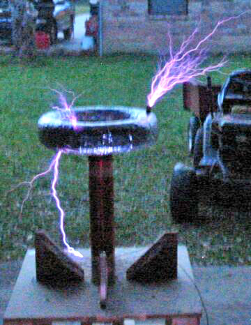
For a variety of technical reasons, toroids provide the best overall
shape for top terminals of modern Tesla coils.
In typical
operation, long, branching high-voltage sparks may strike out in all
directions from the toroid into the air, producing a dangerous, yet
strangely beautiful, lightning-like display of electricity "in
action".
While generating discharges, electrical energy from the secondary and toroid is transferred to the surrounding air as electrical charge, heat, light, and sound.
The electric currents that flow through these discharges are actually due to the rapid shifting of quantities of charge from one place (the top terminal) to other places (nearby regions of air). The process is similar to charging or discharging a capacitor.
The current that arises from shifting charges within a capacitor is called a displacement current.
Tesla Coil discharges are formed as a
result of displacement currents as pulses of electrical charge are
rapidly transferred between the high voltage toroid and nearby
regions within the air (called space charge regions). Although the
space charge regions around the toroid are invisible, they play a
profound role in the appearance and location of Tesla Coil
discharges.
The oscillating primary current creates a magnetic field that couples to the secondary winding, transferring energy into the secondary side of the transformer and causing it to oscillate with the toroid capacitance.
The energy transfer occurs over a number of cycles, and most of the energy that was originally in the primary side is transferred into the secondary side.
The greater the magnetic coupling between windings, the shorter the time required to complete the energy transfer.
As energy builds within the
oscillating secondary circuit, the amplitude of the toroid's RF
voltage rapidly increases, and the air surrounding toroid begins to
undergo dielectric breakdown, forming a corona discharge.
The leader
tapers and branches into thousands of thinner, cooler, hairlike
discharges (called streamers). The streamers look like a bluish
"haze" at the ends of the more luminous leaders, and it's the
streamers that actually transfer charge between the leaders and
toroid to nearby space charge regions. The displacement currents
from countless streamers all feed into the leader, helping to keep
it hot and electrically conductive.
This causes incremental growth of the leader from one pulse to the next, lengthening the entire discharge on each successive pulse.
Repetitive pulsing causes the discharges to grow until the average energy that's available from the Tesla Coil during each pulse balances the average energy being lost in the discharges (mostly as heat).
At this point, dynamic equilibrium is reached, and the discharges have reached their maximum length for the Tesla Coil's output power level. The unique combination of a rising high voltage Radio Frequency envelope and repetitive pulsing seem to be ideally suited to creating long, branching discharges that are considerably longer than would otherwise be expected by output voltage considerations alone.
However, even 100 years later,
there are many aspects of Tesla Coil discharges and the energy
transfer process that are still not completely understood.
Generally, though, Tesla coils are not used for these purposes. Theoretically, a variation of the Tesla coil could utilize the phantom loop effect to form a circuit to induct energy from the earth's magnetic field and other radiant energy.
This concept is part of Tesla's wireless transmission of
electric power distribution system (US1119732 — Apparatus for
Transmitting Electrical Energy — 1902 January 18).
This is often, but mistakenly, interpreted as being due to skin effect, a phenomenon that tends to inhibit alternating current from flowing inside conducting media. Although skin effect is applicable to good electrical conductors (i.e., metals), the skin depth of human flesh at typical Tesla Coil frequencies is still of the order of 60 inches or more.
This means that high frequency currents will still preferentially flow through deeper, better conducting, portions of an experimenter's body such as the circulatory and nervous systems. In reality, a human being's nervous system does not directly sense the flow of potentially dangerous electrical currents above 15–20 kHz; essentially, in order for nerves to be activated, a significant number of ions must cross their membrane before the current (and hence voltage) reverses.
And, since the body no longer provides a warning "shock", novices may touch the output streamers of small Tesla Coils without feeling painful shocks. However, there is anecdotal evidence among Tesla Coil experimenters that temporary tissue damage may still occur as muscle, joint pain, or tingling for hours or even days afterwards.
This is believed to be caused by the
damaging effects of internal current flow, and is especially common
with continuous wave (CW) solid state or vacuum tube type Tesla
Coils.
Doubling the output voltage quadruples the electrostatic energy stored in a given top terminal capacitance.
If an unwary experimenter accidentally places himself in path of the high voltage capacitor discharge to ground, the high current electric shock can cause involuntary spasms of major muscle groups, and may induce life-threatening ventricular fibrillation and cardiac arrest.
Even lower power vacuum tube or solid state Tesla Coils can deliver RF currents that are capable of causing temporary internal tissue, nerve, or joint damage through Joule heating.
In addition, an RF arc can carbonize flesh, causing a painful and dangerous bone-deep RF burn that may take months to heal. Because of these risks, knowledgeable experimenters avoid contact with streamers from all but the smallest systems.
Professionals usually use other means of protection such as a Faraday cage or a chainmail suit to prevent dangerous currents from
entering their body.
Instances and devices
A Magnifier uses a 2-coil "driver" to excite the base of a third coil ("Resonator") that is located some distance from the driver. The operating principles of both systems are similar.
The
world's largest currently existing 2-coil Tesla coil was made by
Greg Leyh. It is a 130,000 watt unit, part of a 38 foot tall
sculpture. It is owned by Alan Gibb and currently resides in a
private sculpture park at Kakanui Point near Auckland, New Zealand.
[1]
The disruptive discharge coil remains in common use as the "ignition coil" or "spark coil" in the ignition system of an internal combustion engine.
A modern variant of the Tesla coil is also used to power plasma globe sculptures and similar devices.
|