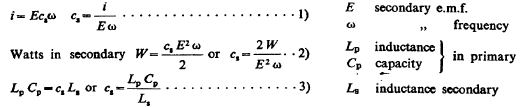
|
Resonance, as evidenced by streamers (maximum) on free end of coil, was obtained exactly as in a previously recorded experiment with 9 jars in each set of the primary condensers, or slightly less, at any rate 8—9 jars caused the largest display of the streamers on the free end. The streamers were only three feet long as the energy from the supply circuit was limited, the intention being to first study the peculiarities and behaviour of the transformers before taking them to their full output.
A simple computation showed that the resonant rise on the free end was chiefly, if not wholly, due to the rise in the coil itself, the free vibration of the secondary being comparatively of small moment. To study the harmonics the capacity in the primary circuit was doubled but the effect, as expected, was very small. Now the capacity in primary was again doubled, it being expected that the streamers would be of considerable power under these conditions. This was the first undertone and it should have been fairly strong.
But singularly nothing to speak of was noted although the adjustments were carefully gone through again and again. It was thought that owing to a very small arc in the primary the oscillation did not readily establish itself but this was not highly probable though such has taken place in experiments which I made before. The arc was necessarily small as the capacity was very large in the primary.
The tuning was very sharp with twice the capacity in primary so that a little variation in the self-induction regulating coil made the streamers change very considerably. I expect that it was sharper still with four times the primary capacity so that, after all, the resonant condition may have been missed. This might have been the case easily as all the variation from no streamers to their maximum would have taken place by going through only one quarter of one turn, and possibly less, of the regulating coil.
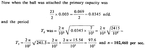
This sharpness of tuning noted here and in previous instances in some arrangements again impresses me with the value of such dispositions in telegraphy, when it is of great importance to isolate messages. It seems possible to secure in such or similar ways an almost absolute privacy. The experiments with only two circuits show this sufficiently. Continuing the experiments one of the balls of 30" diameter was connected to the free end of the coil and now the resonating condition was secured with 23 jars on each side of the primary.
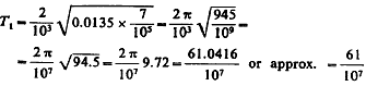
Summing up the results the vibration with coil alone, without ball, with 9 jars on each side of primary was, approximately, taking the primary capacity equal to 9/2 x 0.003= 0.027/ 2 = 0.0135 mfd.
and n = 102,460 per sec.
The ball slows the vibration of the coil very much down. From a
series of observation with capacities of varying value useful
estimates may be made and the quantities of moment calculated. This
mode of proceeding seems to offer features of considerable value in
experimentation and it will be followed up. A curious observation in
these experiments was that maximum rise was obtained always with the
regulating coil practically all out.
Evidently when the coil was cut out there was more energy available for the excitation of the primary turn and therefore the secondary was more strongly energized, this giving a higher electromotive force on its terminals. Owing to this the impressed e.m.f. on the coil attached to the free terminal of secondary was greater and therefore the coil was more strongly excited. Assuming then that the secondary free vibration did not take place, this explanation would be acceptable but for one thing: the maximum rise on the coil with 260 turns did not occur, when all the turns of the primary regulating coil were cut out, but at a point when there remained still a few turns in series with the primary.
The phenomenon must be therefore interpreted differently. To all appearances the secondary free vibration did occur, and there was a certain inductance in the primary which gave the highest e.m.f. on the excited coil on the free terminal of secondary. But now the latter was in fairly close inductive relation with the primary hence its own vibration was more or less modified by that of the primary. In altering the primary vibration, that of the secondary must have been, therefore, correspondingly altered.
Now, the secondary excited the coil with 260 turns and, to insure the maximum rise on the free terminal of the coil, the secondary vibration ought to have been of exactly the same pitch as the free vibration of the coil. From this it is plainly seen that if the primary vibration was such as to favour a rise in the secondary of the pressure at the free terminal then the impressed e.m.f. on the coil with 260 turns was greater; but this evidently, judging from the actually observed results, look place when the secondary vibration was "out of tune", more or less with the free vibration of the coil.
Thus it happened that by raising the secondary e.m.f. up to a certain point there was an increased resonant rise on the excited coil. But when, by further cutting out turns of the regulating primary coil, the secondary vibration was modified more and more and brought "out of tune" with the free vibration of the coil excited by the secondary, the resonant rise on the terminals of the excited coil was diminished.
Now, with a certain small number of turns of the regulating coil still included in the primary, the relation between these opposing elements determining the resonant rise was such as to insure the maximum. I have no doubt that this is the correct explanation of the phenomenon observed. At first I thought that the length of the primary might have something to do with it, as I have observed before something to this effect, but now I must reject this view as improbable.
From the preceding it is now quite evident that in cases when the free vibration of the secondary can assert itself, the primary capacity and self-induction has to be such that maximum e.m.f. is obtained on the secondary — then the excited coil must be such as to vibrate in accord with the secondary or (inasmuch as the secondary vibration is affected by the primary) the free vibration of the excited coil must be the same as that of the combined primary and secondary system.
When the
vibration in the secondary is exactly the same as the free vibration
of the excited coil the maximum rise will be obtained on the coil,
in any event, but for the best result the secondary must also be
tuned to the primary so that greatest impressed e.m.f. is secured on
the coil.
Everything was carefully examined to be quite sure that there was no other ground connection in the secondary. Nevertheless, when the secondary discharge was made to play, strong sparks went continuously over the lightning arresters. There was no other possible way to explain the occurrence of these sparks than to assume that the vibration was propagated through the ground and following the ground wire at another place leaped into the line!
This is certainly extraordinary for it shows more and more clearly that the earth behaves simply as an ordinary conductor and that it will be possible, with powerful apparatus, to produce the stationary waves which I have already observed in the displays of atmospheric electricity. The mere observation of the sparks speaks well for the power of the apparatus used and clearly shows that it is competent to carry to a great distance even as it is when used as a transmitter in telegraphy.
Assume even that the pressure would diminish as the square of the distance from the source, still the performance would be remarkable. Such an assumption seems to be justified when we consider that the density of the current passing over the earth's surface will diminish as the square of the distance from the center of the disturbance and consequently, the effective pressure at least, ought to diminish correspondingly.
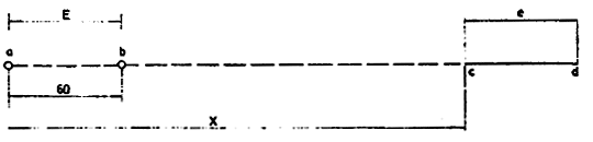
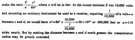
Now, in the experiments above described the distance between point a, where the lower end of the secondary was grounded to point b, where the sparks jumped from the ground to the line or vice versa, was 60 feet. Hence on the above assumption we can
Capacity of secondary 35 turns used in preceding experiments.
The result only shows that the cable measures much more when
straight and at some distance from the ground since d comes out so
large.
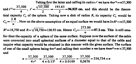
The total capacity C3 of all these small spheres, neglecting mutual screening action, will be n times the capacity of one of the spheres and since the latter is=0.13 we would have total capacity C3=554,734 x 0.13 = 72,115 cm.!
A very large value indeed, which would have been still greater if the diameter of the spheres would have been smaller. These primitive considerations show that to get the largest possible capacity with a given surface we must use the latter in the form of minute surfaces of the smallest possible curvature.
This makes it obvious why exhausted bulbs show under certain conditions such comparatively large capacity. And this explains the virtue of bulbs when used in telegraphy for the purpose of supplanting a large elevated plate or wire leading to a great height. Such a bulb or tube, particularly when filled with hydrogen, is (as I have found) very effective and I look to a valuable use in the future of such rarefied vessels in connection with telegraphy through the media or the like.
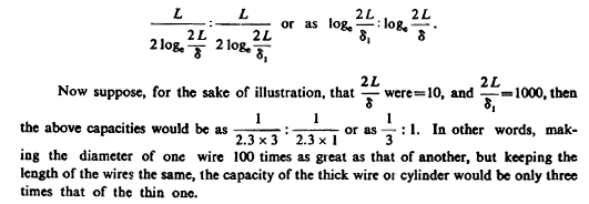
The greatest capacity with a given surface will, of course, be obtained with spheres of the smallest possible diameter, as the spheres of hydrogen. The next best form to give to the surface would be a cylinder of great length and minute diameter. The above considerations make it plain why thin wires have such a comparatively large capacity. Taking two such wires of the same length L and diameters S and &x, we would have their capacities as
Colorado Springs
While this estimate is not correct in principle it shows,
nevertheless, that the capacity measured in a state of rest is not
that which enters as an element of the vibration. It was thought
from this result that the secondary might have responded to the
first octave and the two primary cables were joined in series, but
results proved inferior.
Furthermore, it should be borne in mind that when the cables were in series and the vibration in primary reduced to half the number per second, the induced e.m.f. in the secondary turns could have been only about one half of that in the first experiment. If in the latter experiment with the primaries in series the true note of the secondary was struck then, assuming the capacity to be 3600 cm. or thereabouts, the inductance of the secondary as modified by the primary would have been still only 4x2,939,000=11,765,000 cm.
It is, therefore, probable that the
capacity which enters as an element of the secondary vibration is
much smaller than that which is found by measurement, which is as
might be expected, since the cable can not be fully charged and
discharged at each alternation, as is evident from the constants.
When the secondary worked very well the spark was very noisy and nearly an inch thick, judging by the eye, and about 3 feet long. The sparks passed all the time over the lightning arresters as the secondary discharge was playing and, at times, for a short interval they were extremely vivid and thick. This seemed to occur chiefly when the secondary arc became louder and roaring, this indicating a better working of the arc and a higher e.m.f. for a given length of the path through the ground.
The sparks on the arrester's arc, as is now established beyond any doubt, are due to the propagation to the ground through the earth wire, and it is now plain that although they take place when the oscillation is slow, they are more easily produced with a quicker oscillation. Perhaps the higher harmonics enter prominently into their formation.
The secondary arc was adjusted to a length of 31", then the sparks on the arresters were very violent. It was thought that, if the © vibration was propagated through the earth wire and caused the sparks on the arresters in this way, by adding capacity to the earth wire the action on the arresters would be increased.
Accordingly, a sphere of 12" diam. s was connected to the wire as I shown in diagram and, indeed, the play on the arresters was intensified. By now reducing the gap still a few inches the display on the arresters seemed to increase further. When the secondary discharge was permitted to pass continuously for about 5 minutes the fuse on the supply circuit primary gave way showing that energy was taken at a rate of about 20 H.P.
This also indicated that the
connection between the primary and secondary of the oscillator was
fairly close and that the secondary was capable of taking up
considerable energy. When two external gaps were used in series,
with gaps in box, less energy was taken from the supply circuit,
this indicating that the arc in primary short-circuited the
secondary of W.T. to some extent.
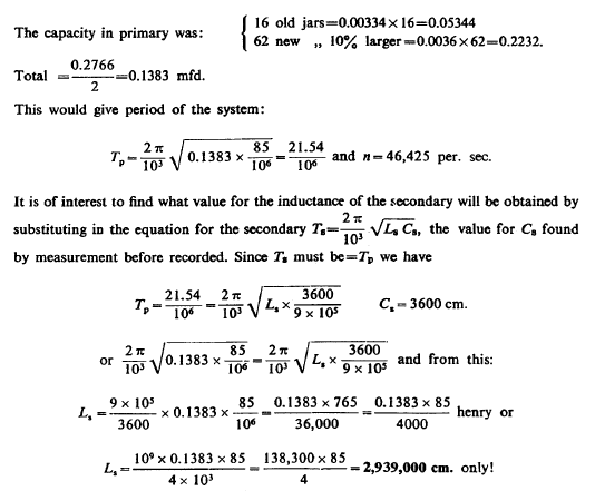
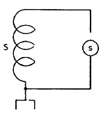
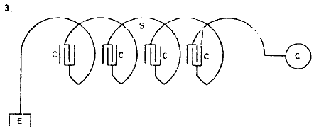
A complete analogy is afforded in mechanics. In order that free vibration may take place, and readily, there must be a loose connection with the part impressing the movement. This truth is obvious. Considerations of this kind led to experimentation with an arrangement, as illustrated in the sketch below: In this the connection with the secondary S impressing the movement was loosened, so to speak, by the insertion between it and the coil C to be excited another coil c which was generally adjusted to suit the conditions.
This amounted to the same as
increasing the momentum of coil C and rendering it more
preponderating and capable of freely asserting itself. These
experiences lead to a rule long recognized, that development of the
oscillator must be in two directions: either in the direction of
obtaining a high impressed electromotive force by transformation
ratio, when the connection between the secondary and primary is
rigid; or obtaining a high e.m.f. by an excited extra coil in loose
connection not reacting inductively.
Thus the loss in the box itself was greatly reduced and owing to the great velocity of separation of the electrodes, a greater suddenness of disruption was obtained. This was, of course, certain since the gaps in the box could not be bridged except for a short interval since gaps a and b took up the e.m.f. Thus the velocity of separation was the greater the smaller (in length) the arcs in the box were made.
The adjustment of their length was effected by merely varying the length of gaps a and b. In these experiments spheres of various sizes were used to constitute the additional gaps a and b and it was observed that unless the induction coil be capable of giving a large current, spheres of considerable size were not the best to employ in the usual arrangement of apparatus.
The reason was that the arc was formed with difficulty, hence it had to be made shorter, but when the current broke through, the resistance of the small arc was very low and the secondary of the induction coil was short circuited too much. This may not be always true. By using additional gaps the primary was closed during a shorter interval of time and also the secondary was less short-circuited. The latter was an advantage but the former was decidedly a disadvantage because the primary circuit could not vibrate very long.
The energy taken from the supply transformer or coil was, of course, smaller. All the results obtained in these experiments seem to indicate, contrary to former opinions, that a higher economy is obtainable with one gap that with a greater number. This observation was, however, made before in the New York apparatus.
Finally, two gaps in series were adopted as convenient and giving greater velocity of separation. But the best results were obtained with two electrodes in the form of toothed disks rotated in opposite directions. The apparatus in this form was more troublesome to run but worked decidedly better. In this form also an improvement was practicable, which I have since adopted in some form of mercury breaks, and that was to make the number of teeth on each disk such that the total number of the makes and breaks was the product of both the numbers.
In this form a small number of teeth was found
sufficient for a great number of breaks and the arc could not follow
from one to an adjacent tooth.
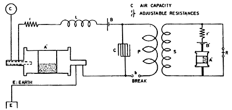
The sensitive devices A and A' were prepared as described on a previous occasion and showed, unexcited, a resistance of over 1,000,000 ohms, but when excited the resistance fell in both almost exactly to fifty ohms.
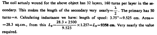
Later, instead of the device A' another was employed of a higher resistance when in the excited state and the coil P S was replaced by one with more turns in the secondary. As finally adopted the secondary S had 160 turns in each layer and 32 layers making 5120 turns.
The relay R had a resistance of 998 ohms, wire No. 36. The primary P had 50 turns of lamp cord No. 20. The self-induction coil L had 1900 turns of wire No. 20. All coils were wound on spools 4" diam., 4" long with wooden core 1 1/4" in center. The condenser C and 1/2 mfd. Battery B: 8 cells 11.1 volts; Battery B': 4 cells about 5.7 volts. Speed of rotation of the devices A and A' was about 24 per minute. The break b was 72 per second.
The break
wheel and arbors of devices A A' being driven by clockwork. The
break wheel has 180 teeth, a small very thin platinium brush bearing
on it. The devices readily responded when four persons joining hands
would shunt the device A'. In one instance the devices recorded
effects of lightning discharges fully 500 miles away, judging from
the periodical action of the discharges as the storm moved away.
Colorado Springs
The coil was connected to the free end of the secondary and resonance was observed with 32 jars on each side, there being on each side two tanks in series, so that the total capacity was only 4 jars in the primary. Taking the capacity of one jar at 0.00334 mfd. the total primary capacity was 4x0.00334=0.01336 mfd.
First the Westinghouse transformer was connected to give 15,000 volts, but later it was made to give 22,500 volts. The capacity in the primary was evidently too small for the best working of the transformer and the arc schort-circuited the secondary considerably, this causing a great deal of energy to be drawn from the supply circuit. This is always the case when the primary arc does not work well.
To insure the best working conditions the transformer should first be able to charge the condensers and the rate of energy delivery of the latter into the primary of the oscillator should be just a little greater than the rate of energy supply by the feeding transformer. Then the arc is loud and sharp and there is no short circuit on the secondary of the latter transformer as the currents over the gap are of very high frequency and the low frequency current of supply — or if it be a direct current — can not follow.
The system then works economically and the economy is much greater than might be supposed judging from the unavoidable losses in the arc. As the capacity was too small a flaming arc often formed in the box, a sure sign of bad working, the curious feature being that the arc was of a decidedly red color. This may be due to the alumina which was formed as the break wheel was of aluminium.
As was expected, the use of two additional gaps improved the working of the apparatus, reducing the trouble due to the short-circuiting of the Westinghouse transformer. It was observed that when the gaps were made so large that the arc did not break through, a lamp on the supply circuit near the condensers — about 6 feet from the same — would brighten up. I am not quite sure that this was due to resonant rise in the Westinghouse transformer, for it may have been due simply to electrostatic action from the jars, as I have observed a similar effect before.
When the electrostatic influence is strong the gas in the bulb is excited, the discharge passing through the same though, of course, it is not visible on account of the intense light of the filament. Particles are thrown off and against the carbon and the same is, on the one hand heated to a higher temperature while on the other hand, owing to the hotter environing medium it can not give the heat away so fast as normally — hence it brightens up.
Possibly also a small part of the current of supply passes through the excited gas and slightly more energy is drawn from the mains. It was evident that, as was expected, the free vibration of the coil took place more readily than before when the coil with 260 turns was used, owing to the larger momentum as before explained.
The streamers were larger than with the old coil but not
quite so large as it was surmised they would be. Partially because
of this fact, and partially also because not enough energy could be
supplied from the Westinghouse transformer to the primary, owing to
the small primary capacity, it was decided to change the connection
so as to get the next lower or fundamental tone in the primary, this
being in all probability the true note of the coil. The capacity in
the primary was made 32 jars on each side in multiple,
making the total capacity 16x0.00334=0.05284 mfd.
Accordingly, the same vibration was again secured in the primary but this time by using a capacity four times larger and reducing the inductance to one fourth, which was done by putting the two primaries in multiple. Now, indeed, the results were satisfactory, for the Westinghouse transformer could supply much more energy, practically four times as much as before.
The streamers were now much stronger, extending to a distance of 6 1/2 feet from the top of the coil and they were abundant and thick. I can not understand why they should be of such a deeply red color. Those in New York never were such. Perhaps it is due to the smaller atmospheric pressure in this locality. Their movement, and darting about is also much quicker and more explosion like.
At times a big cluster of them
would form and spatter irregularly in all directions. Sometimes it
appeared as if a ball would form above the coil, but this may have
been only an optical effect caused by many streamers passing from
various points in different directions. Many times sparks passed
from the top of the coil to the point where the lower end of the
coil was connected to the secondary "free" terminal. These sparks
were 8'—9' long.
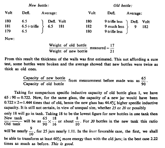
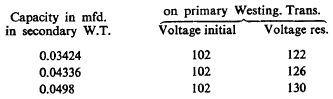
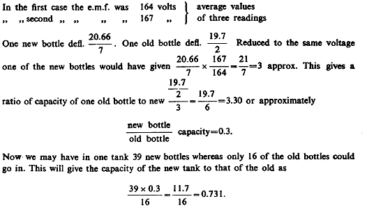
The comparison of capacities was made today for this purpose. The new bottles were filled up to 10" from the bottom and immersed in a tin tank. The old bottles were filled up to 9" from the bottom and immersed in a tank. A solution was prepared from rock salt as concentrated as practicable and care was taken that the liquid was at equal height outside and inside. The readings were:
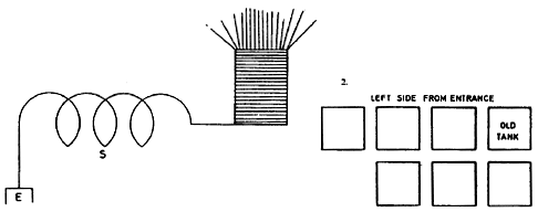
Resonance was obtained with 7 tanks of capacity on each side of the primary. As it was thought that the tanks might perceptibly differ in capacity Diagram 2. is added showing their position. The primary capacity total was from approx. 0.04336 — 0.0498 mfd., according to connections. The effects observed were in many ways interesting. The streamers produced on top of the coil were generally seven feet and sometimes eight feet long, thick and violently darting about.
They did not seem so red as those produced before under similar conditions. Very often strong brilliant sparks would pass from top to bottom of the coil. The remarkable feature of the sparks was that they would go in a curve, almost a semicircle, as if they would start out originally in another direction and then be deflected to the lower end of the coil.
Certainly they could have reached the lower end by a route shorter by 40 or 50%. During the display it was observed that no sparks passed over the lightning arresters. This was an indication that only a comparatively small electromotive force per unit length of ground was set up, too small to bridge the gaps on the arresters. In order to see whether the coil would respond to the next fundamental tone the primary cables were joined in series, this making the frequency of the primary oscillations just one half. The coil did respond but the effect was, as anticipated, small, about one quarter.
Presently one of the large balls, 30" diam, with a wire of some 20 feet was connected to the top end of the coil. The self-induction coil being adjusted, very strong streamers were now obtained showing that the ball had reduced the period of the coil considerably. But the vibration of the coil with the ball was still too fast for the primary and another ball, 30" diam. was connected in multiple with the first. By again adjusting the regulating coil good resonating action was obtained.
The sparks and streamers were now
stronger, the former passing sometimes to the top of the secondary,
a distance of
The sparks were much fuller, thicker and louder with the balls then without them, they were particularly strong and bright when passing from top to bottom of the coil. It was plain that much longer sparks could be obtained with more turns in the extra coil as then the capacity on the end could be reduced. But the experiments also showed that the amount of electrical movement in the coil was not very great owing to the small section of the wire, for when an arc was established between two large balls it ceased to pass as soon as they were separated a distance of about 1 foot.
The streamers were visible and sometimes strong on the wires leading to the balls' and particularly on the wire leading from the top of the coil but still the sparks failed to bridge the gap. This showed that there was not enough energy available to charge the balls to a sufficiently high potential while, of course, the passage of the sparks was rendered more difficult owing to the large radius of the curvature.
The
density ought to be inversely as the radius of the curvature, hence
the density on the wire leading to the ball is much greater than on
the ball itself, in other words, which really means the same, the
ball is charged to a lower potential than the wire. This seems to me
a somewhat novel view to take. Without much thought I would at once
assume that the pressure on the ball and on the wire is the same,
but it must be greater on the wire since it can leak out from the
same while it does not from the ball.
In signalling to a distance, the formation of a streamer on the transmitter impairs very materially its effectiveness so that the signals sometimes do not go more than a quarter of the distance or even less just on this account. By using a body of considerable surface, which should be spherical or a cylinder with hemispherical ends better results are obtained than with a wire leading to a height alone, not so much because of the increased capacity, but generally only because there is less opportunity for a leak and the system is more economical in producing an electrical vibration in the ground.
A large sphere or
surface, provided it is not too large as to interfere with the
vibration of the transmitting system is better than a small one for
the same reasons.
One obvious cause of this is that usually in such a case pL/R is larger than if the conductors are not of great mass, but as far as I have been able to judge, the chief reason is that an electromotive force, acting upon a circuit so constituted, must give rise to a much greater current, in the first moment when in any manner, as by the passage of a spark, a great and very sudden variation in the electromotive force acting in the system is produced. I make a distinction between these two effects. One raises the pressure gradually, the other is responsible for the great suddenness.
Thus,
a mass of metal of minute electrical resistance behaves towards a
sudden manifestation of electrical pressure much in the same manner
as a mass of metal of great inertia behaves towards a sudden pressure caused by a blow. In both cases there is
an increase of the pressure or force. When in the experiments,
presently described, a small wire was attached to one of the balls,
the other ball being left as before, the sparks passed readily
between them at a distance of 6 1/2—7 feet.
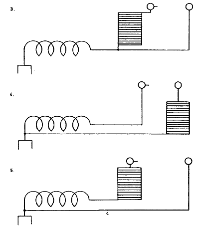
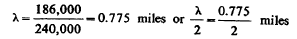
The connection as first used, which is illustrated in Diagram 3. was now changed into the one shown in Diagram 4.
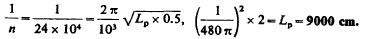
Although the coil was now excited by a small impressed e.m.f. the sparks between the balls were nevertheless quite strong reaching more than 2 1/2 feet. This showed that there was also an induced e.m.f. cooperating with the impressed e.m.f. in the coil to bring about the great rise. Diagram 4. suggested the connecting of the lower end of the excited coil to any other point of the secondary thus regulating the impressed e.m.f. at will.
Again, in the connection as shown in Diagram 4.,
there were no sparks on the arresters, for the reason pointed out.
But when the connection illustrated in Diagram 5. was made, they
appeared and became stronger when conductor c was constituted by a
very heavy cable. This was to be expected from the above. It
demonstrated the obvious fact that short waves are more effective
giving higher e.m.f. per unit of length in the ground.
It was desirable to have an induction coil the secondary system of which would vibrate with the same period if possible, and a coil was wound on spool the dimensions of which are indicated in diagram. Now the system being 240,000=/!, this gives the wave length
or 2000 feet approx. The average length of one secondary turn is a little over 4.5", this will therefore require a little over 5000 turns. Now it is desired to use the 1 /2 mfd. condenser on hand for the primary of the coil. The primary must have the same period, hence we have to find the inductance of primary
Note: It will be better, of course, to adopt plan used in New York
and design coil with a lot of cooper.
On each side of the primary there were then 2 sets in
series, the connections in one instance being indicated in diagram.
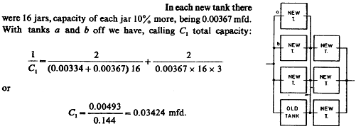
In each old tank there were 16 jars, 7. the capacity of each jar
being 0.00334mfd. In each new tank there
were 16 jars, capacity of each jar 10% more, being 0.00367 mfd.
With this capacity on the secondary of the Westinghouse transformer the rise on the primary, as observed by Weston voltmeter, was from 102 to 122 volts. With tank b on each side added, the total capacity being C2, we have:
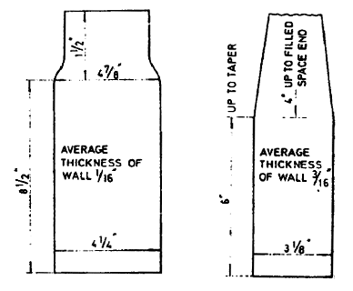
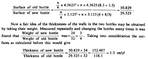
Now mean diam. of cylindrical part of old jar outside =4.5625". Now
mean diam. of cylindrical new bottle jar outside=3.125". Allowance
for upper part on old jar 1 1/2" taken of same diam. as cylindrical
or nearly cylindrical part.
Since the thickness ratio is much greater as found in this way the determination of the thickness by weight as above is not practicable without making allowances. The glass is evidently uneven, much more so in the old bottles than in the new. In the former particularly the bottom is heavy which vitiates the result inferred from the weight of the bottles.
Many bottles were broken and it was ascertained that the average thickness of new bottles was three times that of the old. It was quite certain at any rate, that the weakest spot on the new bottle was fully three times the thickness of the weakest spot on the old.
This was the most important thing to ascertain for the bottles give way at the weakest place. Now since the capacity of the old bottle in relation to that of the new is found by measurement to be 1 : 0.3 approx. and the surfaces are as 50.829/29.525 we can get an idea of the specific inductive capacity of the latter with respect to that of the former.
The new bottle would have for the same
thickness, that is one third of the actual, 0.9 instead of 0.3 and
for the same surface it would have
50.829/29.525xO.9 or 1.55 times the capacity
of the old, both things considered so that the specific inductive capacity of
the glass in the new bottle must be something like 55% greater than
that of the glass in the old bottle.
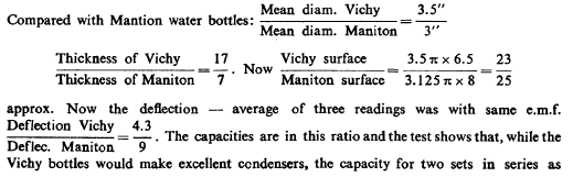
The capacities are in this ratio and the test shows that, while the Vichy bottles would make excellent condensers, the capacity for two sets in series as desired would be too small. The reason is that the wall is unnecessarily thick. If it were convenient to use only one set of condensers nothing better could be desired. It having been practically decided to adopt the Maniton bottles, tests were made to see how much pressure these bottles would stand safely.
Accordingly 7 of these bottles with wall rather weaker than normal, hardly 1/8" thick, were placed in a tank with the other bottles. The concentrated salt solution reached to a point about 3" from the top. Paraffin oil was poured to nearly the top. First 7500 volts were turned on, then the tension was raised up to 15,000 volts and the bottles withstood. The e.m.f. was then raised to 22,500 volts when the bottles began to give way, three being broken after some time.
The conclusion was that two sets of bottles in series would
withstand quite safely at least 30,000 volts. The glass is really
excellent. These tests were made with 144 cycles per second. A
curious observation was that when one bottle gave way others
followed, this being due to the violent oscillations caused or else
to the concussion upon explosion.
The adjacent portion of the wire acts like a condenser in which energy is stored at each alternation, and the amount of this stored energy is proportionate to the square of the difference of potential existing between the portions of the wire constituting the condenser. Now most of this movement of electricity, occasioned by this distributed capacity, takes place within the coil and does not, unless in a very small part, appear in the external circuit.
Since the movement in the latter circuit is
the chief object, the charging and discharging of the condensers
formed by the turns of the coil is mostly lost for the purpose for
which the machine is designed. In a properly designed oscillator of
this kind all the movement produced in the coil should be propagated
to the external circuit, but this condition can never be rigorously
realized.
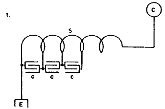
Such a coil S with considerable distributed capacity will, therefore, not be efficient in producing disturbances such as I contemplate using for a number of purposes. The distributed capacity is particularly hurtful when it is desired to produce a very high potential at C and, as this is generally the case, it is important to adopt a construction and observe working conditions such as will reduce the evil to the minimum.
I have in similar instances attained the object more or less by constructing a secondary in parts connected in series through condensers, and' a secondary to suit the present apparatus designed on this plan is now to be considered. In order to explain better how such condensers in series act in reducing the effect of distributed capacity, as pointed out before, reference is made to Diagram 2. which shows turns or portions of the secondary connected through condensers c, c, c.
Suppose there would be n such parts as t joined in series and let C, be the total capacity of the coil or secondary S, then the capacity of the turns or portion / would be —.
But now, if there be on the ends of this portion t condensers n C, and C2 it is plain that the distribution of electricity along the portion t will be greatly modified by the presence of these condensers and, if their capacity be very much greater than that of the wire f, almost all of the electricity will reside on the coatings of the condensers, hence there will be very little local action in the portion t, and most of the electrical movement created in the wire will be transmitted along the entire length of the same from E to C and vice versa.
The machine will then act more efficiently and will be much more suitable for the transmission of energy through the terminals E and C for whatever purpose the energy be intended and in whatever manner it be used. It should be stated that in the particular form of oscillator as here illustrated, the lower turns of portions which are closer to the earth, and therefore at a lower potential, are not nearly as hurtful as the upper ones, or to put it more generally, those which are farther away from the earth connection and closer to the free terminal.
The latter are, namely, at a much higher potential and there exists generally a greater difference of potential between portions of wire of the same length when the resonant rise is considerable; as the energy stored in the distributed condensers is proportionate, as before stated, to the square of the difference of the pressure between adjacent portions, it is, as a rule, of advantage to make the upper turns of smaller diameter or to put them farther apart.
But in certain instances this very
drawback can be turned into an advantage and by placing a few of the
turns near terminal C
Coming now to the consideration of the secondary to be modified in the manner proposed let Diagram 3. illustrate the arrangement as contemplated in the present instance, a condenser C being placed between each succeeding turn of secondary S.
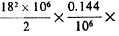
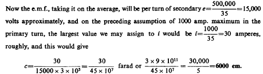
I shall make a rough estimate on the basis of one primary turn and the maximum primary capacity available, which is 80 jars on each side giving a total capacity of 40 jars or 40 x 0.0036= =0.144 mfd. approx,, there being two sets in series. This would give n=50,000 per second roughly.
Assume we work with 30,000 volts from the Westinghouse transformer and retain, as at present, 35 turns of the secondary. In this case, considering the distance of the secondary turns and their decreasing diameter, the induced e.m.f. in the secondary will be much smaller than might be inferred from the ratio of transformation which will be 35 :1 ; with reference to measurements of mutual inductance made before, with a secondary wound on the same frame, it may be estimated at 18 times the primary e.m.f., that is, the induced e.m.f. in the secondary may be assumed to be 18x30,000=500,000 volts nearly.
Taking the number of breaks at 1200 per second as used in some of the preceding experiments with the apparatus, and assuming the charge of condensers always effected at an average pressure, say 6/10 of 30,000 or 18,000 volts, the energy stored in the condensers per second and delivered in the primary will be
that is nearly 38 H.P. will be taken
by the apparatus under these conditions. This is, of course, only an
approximate estimate. We may now, on this basis, estimate the
current through the Westinghouse transformer's secondary, which will be roughly estimated
R is difficult to estimate since the primary circuit includes the arc over the spark gap. I have adopted a method for determining the resistance of the arc with fair accuracy and this will be the subject of a later consideration. The resistance of the Primary cables in multiple is entirely negligible, there being in each 37 wires, No. 9. Taking 1265 feet per ohm, the resistance of about 160 feet of such two cables would be
While, of course, such a condition can not be realized in practice we may approach this value more or less by doing away with the arc in the primary as, for instance, in the form of an oscillator with mercury breaks, which I have devised to work with low tension so that the arc practically does not occur.
Or a condenser may be placed in shunt to the primary as has been already considered on a previous occasion. By experience I know that the initial currents in the primary reach certainly several thousand amperes showing by this that the resistance of the arc can not be great. For the present I shall assume that it is 18 ohms so that if the condensers are, as supposed above, charged to 18,000 volts during ordinary performance, the initial current would be about 1000 amperes in the primary decreasing logarithmically.
With this maximum in the primary, the loss in this circuit will not be unduly great. Now the secondary condensers should be of a capacity to carry the secondary current at the frequency used. Calling now e the e.m.f. induced in the secondary per turn, c the capacity of one of the secondary condensers as before, we will have the current through the turn i=e c o>, to being here 3x 10s as before assumed.
We would thus require a capacity of about 8000 cm. in each of the
condensers to carry the secondary current in the oscillator. But
this is really too high an estimate and it is quite certain that a
smaller capacity would do. Since a jar has a capacity of 0.0036 x x9
x 105=3240 cm., two jars would be amply sufficient and possibly also
one jar between each turn of the secondary. Taking it on this basis,
the total capacity of the secondary
would be
These secondary condensers will,
of course, have to be so constructed as to withstand not so much the
strain on the dielectric — for this they will support easily — but
the sparking over the condenser coating. Let the spark length on the
secondary be, say, 12 feet and suppose we had 36 secondary
condensers, then on the average they ought to be able to prevent
sparking when the pressure on each is such as to cause a spark of
a length of
The virtue of condensers used in such a manner is well established and I think it resides in the fact that when they are used the charge docs not distribute itself along the wire, but accumulates on the coatings of the condensers thus reducing the effect of mutual electrostatic induction of the adjacent or near positions of the wire, to a large extent, and reducing in this manner the amount of energy stored in the coil itself. It now remains to consider the capacity on the end of the secondary which is "free".
This capacity ought to be so large that it can take up all the current of the secondary at the frequency used. Or, to put it otherwise, it should be able to store all the energy the secondary is able to give. There is, however, another consideration which must be made in case the secondary is capable of free vibration, and that is that the capacity on the end should be so determined as to secure resonance with the primary.
As regards this capacity there are then three relations to be borne in mind when deciding upon this and they are:
This to follow up.
|


 x 1200 watts or 28,000 watts,
 = of an ampere, or with
losses etc., say one 30,000 300 ampere. The performance will thus be
still much below the maximum output of the trans-
= of an ampere, or with
losses etc., say one 30,000 300 ampere. The performance will thus be
still much below the maximum output of the trans-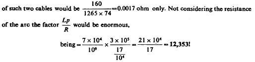
 = 185 cm. approx., while the measured capacity was 3600 cm.
The
effects of distributed capacity would thus be reduced by the use of
secondary condensers to about 5%.
= 185 cm. approx., while the measured capacity was 3600 cm.
The
effects of distributed capacity would thus be reduced by the use of
secondary condensers to about 5%.  There will
not be much difficulty encountered in this respect,
if the condensers are properly designed.
There will
not be much difficulty encountered in this respect,
if the condensers are properly designed.