|
Abstract
The region is excited by electron cyclotron resonance heating to thereby increase its charged particle density. In one embodiment, circularly polarized electromagnetic radiation is transmitted upward in a direction substantially parallel to and along a field line which extends through the region of plasma to be altered.
The radiation is transmitted at a frequency which excites electron cyclotron resonance to heat and accelerate the charged particles.
This increase in energy can cause
ionization of neutral particles which are then absorbed as part of
the region thereby increasing the charged particle density of the
region.
Claims I claim:
The region is excited by electron cyclotron resonance
heating of electrons which are already present and/or artificially
created in the region to thereby increase the charged particle
energy and ultimately the density of the region.
The radiation is transmitted at a frequency which is based on the gyrofrequency of the charged particles and which, when applied to the at least one region, excites electron cyclotron resonance within the region or regions to heat and accelerate the charged particles in their respective helical paths around and along the field line. Sufficient energy is employed to cause ionization of neutral particles (molecules of oxygen, nitrogen and the like, particulates, etc.) which then become a part of the region thereby increasing the charged particle density of the region.
This effect can further be enhanced by
providing artificial particles, e.g., electrons, ions, etc.,
directly into the region to be affected from a rocket, satellite, or
the like to supplement the particles in the naturally-occurring
plasma. These artificial particles are also ionized by the
transmitted electromagnetic radiation thereby increasing charged
particle density of the resulting plasma in the region.
The charged electrons drag ions with them as well as other particles that may be present.
Sufficient power, e.g., 10.sup.15
joules, can be applied so that the altered plasma can be trapped on
the field line between mirror points and will oscillate in space for
prolonged periods of time. By this embodiment, a plume of altered
plasma can be established at selected locations for communication
modification or other purposes.
Once this layer is established, and while maintaining the transmission of the main beam of circularly polarized electromagnetic radiation, the main beam is modulated and/or at least one second different, modulated electromagnetic radiation beam is transmitted from at least one separate source at a different frequency which will be absorbed in the plasma layer.
The amplitude of the frequency of the
main beam and/or the second beam or beams is modulated in resonance
with at least one known oscillation mode in the selected region or
regions to excite the known oscillation mode to propagate a known
frequency wave or waves throughout the ionosphere.
The field lines which intersect the
earth's surface near the poles have apexes which lie at the furthest
points in the earth's magnetosphere while those closest to the
Equator have apexes which reach only the lower portion of the
magnetosphere.
As the gyrating particle moves along a field line in a uniform field, it will follow a helical path about its guiding center, hence linear motion, and will remain on the field line. Electrons and ions both follow helical paths around a field line but rotate in opposite directions.
The frequencies at
which the electrons and ions rotate about the field line are called gyromagnetic frequencies or cyclotron frequencies because they are
identical with the expression for the angular frequencies of
gyration of particles in a cyclotron. The cyclotron frequency of
ions in a given magnetic field is less than that of electrons, in
inverse proportion to their masses.
However, in converging force fields, the pitch angle does change in such a way as to allow the particle to turn around and avoid impact. Consider a particle moving along a field line down toward the earth. It moves into a region of increasing magnetic field strength and therefore sine alpha increases. But sine alpha can only increase to 1.0, at which point, the particle turns around and starts moving up along the field line, and alpha decreases. The point at which the particle turns around is called the mirror point, and there alpha equals ninety degrees.
This process is repeated at the other end of the field line where the same magnetic field strength value B, namely Bm, exists.
The particle again turns around and this is called the "conjugate point" of the original mirror point. The particle is therefore trapped and bounces between the two magnetic mirrors. The particle can continue oscillating in space in this manner for long periods of time.
The actual place where a particle will mirror can be calculated from the following:
Recent discoveries have established that there are substantial regions of naturally trapped particles in space which are commonly called "trapped radiation belts".
These
belts occur at altitudes greater than about 500 km and accordingly
lie in the magnetosphere and mostly above the ionosphere.
The charged particles which form this plasma move between collisions with other particles along similar helical paths around the field lines and although a particular particle may diffuse downward into the earth's lower atmosphere or lose energy and diverge from its original field line due to collisions with other particles, these charged particles are normally replaced by other available charged particles or by particles that are ionized by collision with said particle.
The
electron density (N.sub.e) of the plasma will vary with the actual
conditions and locations involved. Also, neutral particles, ions,
and electrons are present in proximity to the field lines.
If a plasma
is confined by a static axial magnetic field of strength B, the
charged particles will gyrate about the lines of force with a
frequency given, in hertz, as f.sub.g =1.54.times.10.sup.3 B/A,
where: B=magnetic field strength in gauss, and A=mass number of the
ion.
The radio-frequency radiation produces time-varying fields (electric and magnetic), and the electric field accelerates the charged particle. The energized electrons share their energy with ions and neutrals by undergoing collisions with these particles, thereby effectively raising the temperature of the electrons, ions, and neutrals.
The apportionment of energy among these
species is determined by collision frequencies. For a more detailed
understanding of the physics involved, see "Controlled Thermonuclear
Reactions", Glasstone and Lovberg, D. Van Nostrand Company, Inc.,
Princeton, N.J., 1960 and "The Radiation Belt and Magnetosphere",
Hess, Blaisdell Publishing Company, 1968, both of which are
incorporated herein by reference.
FIG. 1 is a simplified illustration of
the earth 10 and one of its dipole magnetic force or field lines 11.
As will be understood, line 11 may be any one of the numerous
naturally existing field lines and the actual geographical locations
13 and 14 of line 11 will be chosen based on a particular operation
to be carried out. The actual locations at which field lines
intersect the earth's surface is documented and is readily
ascertainable by those skilled in the art.
These electrons may be already present in the atmosphere, ionosphere, and/or magnetosphere of the earth, or can be artificially generated by a variety of means such as x-ray beams, charged particle beams, lasers, the plasma sheath surrounding an object such as a missile or meteor, and the like.
Further, artificial particles, e.g., electrons, ions, etc., can be injected directly into region R from an earth-launched rocket or orbiting satellite carrying, for example, a payload of radioactive beta-decay material; alpha emitters; an electron accelerator; and/or ionized gases such as hydrogen; see U.S. Pat. No. 4,042,196.
The altitude can be greater than about
50 km if desired, e.g., can be from about 50 km to about 800 km,
and, accordingly may lie in either the ionosphere or the
magnetosphere or both. As explained above, plasma will be present
along line 11 within region R and is represented by the helical line
12. Plasma 12 is comprised of charged particles (i.e., electrons and
ions) which rotate about opposing helical paths along line 11.
See "The MST Radar
at Poker Flat, Alaska", Radio Science, Vol. 15, No. 2, Mar.-Apr.
1980, pps. 213-223, which is incorporated herein by reference.
Antenna 15 is coupled to transmitter 16 which generates a beam of
high frequency electromagnetic radiation at a wide range of discrete
frequencies, e.g., from about 20 to about 1800 kilohertz (kHz).
Although the electrical generators necessary for the practice of the invention can be powered in any known manner, for example, by nuclear reactors, hydroelectric facilities, hydrocarbon fuels, and the like, this invention, because of its very large power requirement in certain applications, is particularly adapted for use with certain types of fuel sources which naturally occur at strategic geographical locations around the earth.
For example, large reserves of hydrocarbons (oil and natural gas) exist in Alaska and Canada.
In northern Alaska, particularly the North Slope region, large reserves are currently readily available. Alaska and northern Canada also are ideally located geographically as to magnetic latitudes. Alaska provides easy access to magnetic field lines that are especially suited to the practice of this invention, since many field lines which extend to desirable altitudes for this invention intersect the earth in Alaska.
Thus, in Alaska, there is a unique combination of large, accessible fuel sources at desirable field line intersections. Further, a particularly desirable fuel source for the generation of very large amounts of electricity is present in Alaska in abundance, this source being natural gas. The presence of very large amounts of clean-burning natural gas in Alaskan latitudes, particularly on the North Slope, and the availability of magnetohydrodynamic (MHD), gas turbine, fuel cell, electrogasdynamic (EGD) electric generators which operate very efficiently with natural gas provide an ideal power source for the unprecedented power requirements of certain of the applications of this invention.
For a more detailed discussion of the various means for generating electricity from hydrocarbon fuels, see "Electrical Aspects of Combustion", Lawton and Weinberg, Clarendon Press, 1969. For example, it is possible to generate the electricity directly at the high frequency needed to drive the antenna system.
To do this, typically the velocity of flow of the combustion gases (v), past magnetic field perturbation of dimension d (in the case of MHD), follow the rule:
Put another way, in Alaska, the right type of fuel (natural gas) is naturally present in large amounts and at just the right magnetic latitudes for the most efficient practice of this invention, a truly unique combination of circumstances.
Desirable magnetic latitudes for the practice of this invention
interest the earth's surface both northerly and southerly of the
equator, particularly desirable latitudes being those, both
northerly and southerly, which correspond in magnitude with the
magnetic latitudes that encompass Alaska.
To accomplish this result, electromagnetic radiation is transmitted at the outset, essentially parallel to line 11 via antenna 15 as right hand circularly polarized radiation wave 20. Wave 20 has a frequency which will excite electron cyclotron resonance with plasma 12 at its initial or original altitude.
This frequency will vary depending on the electron cyclotron resonance of region R.sub.1 which, in turn, can be determined from available data based on the altitudes of region R.sub.1, the particular field line 11 being used, the strength of the earth's magnetic field, etc.
Frequencies of from about 20 to about 7200 kHz, preferably from about 20 to about 1800 kHz can be employed. Also, for any given application, there will be a threshhold (minimum power level) which is needed to produce the desired result.
The minimum power level is a function of the level
of plasma production and movement required, taking into
consideration any loss processes that may be dominant in a
particular plasma or propagation path.
As the electron energy is raised to values of about 1
kilo electron volt (kev), the generated mirror force (explained
below) will direct the excited plasma 12 upward along line 11 to
form a plume R.sub.2 at an altitude higher than that of R.sub.1.
Since the magnetic field is divergent in region R.sub.1, it can be shown that the plasma will move upwardly from the heating region as shown in FIG. 1 (above right) and further it can be shown that,
Equation (3) ignores electron kinetic energy parallel to B because V.sub.e.parallel. .apprxeq.V.sub.i.parallel., so the bulk of parallel kinetic energy resides in the ions because of their greater masses.
For example, if an electromagnetic energy flux of from about 1 to about 10 watts per square centimeter is applied to region R, whose altitude is 115 km, a plasma having a density (N.sub.e) of 10.sup.12 per cubic centimeter will be generated and moved upward to region R.sub.2 which has an altitude of about 1000 km.
The movement of electrons in the plasma is due to the mirror force while the ions are moved by ambipolar diffusion (which results from the electrostatic field). This effectively "lifts" a layer of plasma 12 from the ionosphere and/or magnetosphere to a higher elevation R.sub.2. The total energy required to create a plasma with a base area of 3 square kilometers and a height of 1000 km is about 3.times.10.sup.13 joules.
Electrons (e) are accelerated to velocities required to generate the necessary mirror force to cause their upward movement. At the same time neutral particles (n) which are present along line 11 in region R.sub.1 are ionized and become part of plasma 12.
As electrons (e) move upward along line 11, they drag ions (i) and neutrals (n) with them but at an angle .theta. of about 13 degrees to field line 11. Also, any particulates that may be present in region R.sub.1, will be swept upwardly with the plasma. As the charged particles of plasma 12 move upward, other particles such as neutrals within or below R.sub.1, move in to replace the upwardly moving particles.
These neutrals, under some
conditions, can drag with them charged particles.
The plasma 12 will then form a plume (cross-hatched area in FIG. 2) which will be relatively stable for prolonged periods of time. The exact period of time will vary widely and be determined by gravitational forces and a combination of radiative and diffusive loss terms. In the previous detailed example, the calculations were based on forming a plume by producing 0.sup.+ energies of 2 ev/particle.
About 10 ev per particle would be required to expand plasma 12 to apex point C (FIG. 1).
There at least some of the particles of plasma 12 will be trapped and will oscillate between mirror points along field line 11. This oscillation will then allow additional heating of the trapped plasma 12 by stochastic heating which is associated with trapped and oscillating particles.
See "A New
Mechanism for Accelerating Electrons in the Outer Ionosphere" by R.
A. Helliwell and T. F. Bell, Journal of Geophysical Research, Vol.
65, No. 6, June, 1960. This is preferably carried out at an altitude
of at least 500 km.
Likewise, if the density N.sub.e is on the order of 10.sup.8, a properly positioned plume will provide a reflecting surface for VHF waves and can be used to enhance, interfere with, or otherwise modify communication transmissions. It can be seen from the foregoing that by appropriate application of various aspects of this invention at strategic locations and with adequate power sources, a means and method is provided to cause interference with or even total disruption of communications over a very large portion of the earth.
This invention could be employed to disrupt not only land based communications, both civilian and military, but also airborne communications and sea communications (both surface and subsurface). This would have significant military implications, particularly as a barrier to or confusing factor for hostile missiles or airplanes.
The belt or belts of enhanced ionization produced by the method and apparatus of this invention, particularly if set up over Northern Alaska and Canada, could be employed as an early warning device, as well as a communications disruption medium.
Further, the simple ability to produce such a situation in a practical time period can by itself be a deterring force to hostile action.
The ideal combination of suitable field lines intersecting the earth's surface at the point where substantial fuel sources are available for generation of very large quantities of electromagnetic power, such as the North Slope of Alaska, provides the wherewithal to accomplish the foregoing in a practical time period, e.g., strategic requirements could necessitate achieving the desired altered regions in time periods of two minutes or less and this is achievable with this invention, especially when the combination of natural gas and magnetohydrodynamic, gas turbine, fuel cell and/or EGD electric generators are employed at the point where the useful field lines intersect the earth's surface.
One feature of this invention which satisfies a basic requirement of a weapon system, i.e., continuous checking of operability, is that small amounts of power can be generated for operability checking purposes.
Further, in the
exploitation of this invention, since the main electromagnetic beam
which generates the enhanced
This can cause confusion of or interference with or even complete disruption of guidance systems employed by even the most sophisticated of airplanes and missiles. The ability to employ and transmit over very wide areas of the earth a plurality of electromagnetic waves of varying frequencies and to change same at will in a random manner, provides a unique ability to interfere with all modes of communications, land, sea, and/or air, at the same time.
Because of the unique juxtaposition of usable fuel source at the point where desirable field lines intersect the earth's surface, such wide ranging and complete communication interference can be achieved in a reasonably short period of time.
Because of the mirroring phenomenon discussed hereinabove, it can also be prolonged for substantial time periods so that it would not be a mere transient effect that could simply be waited out by an opposing force.
Thus, this invention provides the ability to put unprecedented amounts of power in the earth's atmosphere at strategic locations and to maintain the power injection level, particularly if random pulsing is employed, in a manner far more precise and better controlled than heretofore accomplished by the prior art, particularly by the detonation of nuclear devices of various yields at various altitudes.
Where the prior art approaches yielded merely transitory effects, the unique combination of fuel and desirable field lines at the point where the fuel occurs allows the establishment of, compared to prior art approaches, precisely controlled and long-lasting effects which cannot, practically speaking, simply be waited out.
Further, by knowing the frequencies of the various electromagnetic beams employed in the practice of this invention, it is possible not only to interfere with third party communications but to take advantage of one or more such beams to carry out a communications network even though the rest of the world's communications are disrupted.
Put another way, what is used to disrupt another's communications can be employed by one knowledgeable of this invention as a communications network at the same time. In addition, once one's own communication network is established, the far-reaching extent of the effects of this invention could be employed to pick up communication signals of other for intelligence purposes.
Thus, it can be seen that the disrupting effects achievable by this invention can be employed to benefit by the party who is practicing this invention since knowledge of the various electromagnetic waves being employed and how they will vary in frequency and magnitude can be used to an advantage for positive communication and eavesdropping purposes at the same time.
However, this invention is not limited
to locations where the fuel source naturally exists or where
desirable field lines naturally intersect the earth's surface. For
example, fuel, particularly hydrocarbon fuel, can be transported by
pipeline and the like to the location where the invention is to be
practiced.
Electromagnetic radiation is transmitted at the outset essentially parallel to field line 11 via antenna 15 as a right hand circularly polarized wave and at a frequency (e.g., 1.78 megahertz when the magnetic field at the desired altitude is 0.66 gauss) capable of exciting electron cyclotron resonance in plasma 12 at the particular altitude of plasma 12.
This causes heating of the particles
(electrons, ions, neutrals, and particulates) and ionization of the
uncharged particles adjacent line 11, all of which are absorbed into
plasma 12 to increase the density thereof. The power transmitted,
e.g., 2.times.10.sup.6 watts for up to 2 minutes heating time, is
less than that required to generate the mirror force F required to
move plasma 12 upward as in the previous embodiment.
The electromagnetic radiation wave from antenna 32 is amplitude modulated to match a known mode of oscillation f.sub.3 in layer 30. This creates a resonance in layer 30 which excites a new plasma wave 33 which also has a frequency of f.sub.3 and which then propagates through the ionosphere. Wave 33 can be used to improve or disrupt communications or both depending on what is desired in a particular application.
Of course, more than
one new wave 33 can be generated and the various new waves can be
modulated at will and in a highly nonlinear fashion.
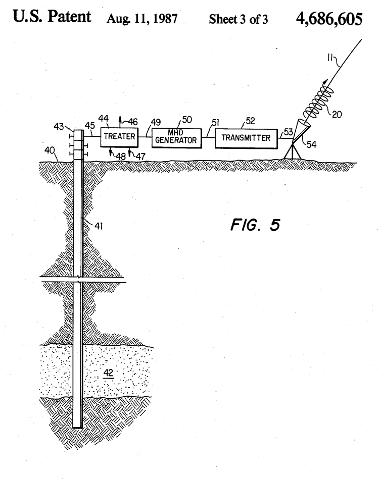
In FIG. 5 there is shown the earth's surface 40 with a well 41 extending downwardly thereinto until it penetrates hydrocarbon producing reservoir 42. Hydrocarbon reservoir 42 produces natural gas alone or in combination with crude oil.
Hydrocarbons are produced from reservoir 42 through well 41 and wellhead 43 to a treating system 44 by way of pipe 45.
In treater 44, desirable liquids such as crude oil and gas condensates are separated and recovered by way of pipe 46 while undesirable gases and liquids such as water, H.sub.2 S, and the like are separated by way of pipe 47.
Desirable gases such as carbon dioxide are separated by way of pipe 48, and the remaining natural gas stream is removed from treater 44 by way of pipe 49 for storage in conventional tankage means (not shown) for future use and/or use in an electrical generator such as a magnetohydrodynamic, gas turbine, fuel cell or EGD generator 50.
Any desired number and combination of different types of electric generators can be employed in the practice of this invention. The natural gas is burned in generator 50 to produce substantial quantities of electricity which is then stored and/or passed by way of wire 51 to a transmitter 52 which generates the electromagnetic radiation to be used in the method of this invention.
The electromagnetic radiation is then passed by way
of wire 53 to antenna 54 which is located at or near the end of
field line 11. Antenna 54 sends circularly polarized radiation wave
20 upwards along field line 11 to carry out the various methods of
this invention as described hereinabove.
Further, this can all be accomplished in a relatively small physical area when there is the unique coincidence of fuel source 42 and desirable field line 11. Of course, only one set of equipment is shown in FIG. 5 for sake of simplicity. For a large hydrocarbon reservoir 42, a plurality of wells 41 can be employed to feed one or more storage means and/or treaters and as large a number of generators 55 as needed to power one or more transmitters 52 and one or more antennas 54.
Since all of the apparatus 44 through 54 can be employed and used essentially at the sight where naturally-occurring fuel source 42 is located, all the necessary electromagnetic radiation 20 is generated essentially at the same location as fuel source 42.
This provides for a maximum amount of
usable electromagnetic radiation 20 since there are no significant
storage or transportation losses to be incurred. In other words, the
apparatus is brought to the sight of the fuel source where desirable
field line 11 intersects the earth's surface 40 on or near the
geographical location of fuel source 42, fuel source 42 being at a
desirable magnetic latitude for the practice of this invention, for
example, Alaska.
Thus, the use of fuel source 42 to generate a plasma by combustion thereof for the generation of electricity essentially at the site of occurrence of the fuel source is unique and ideal when high power levels are required and desirable field lines 11 intersect the earth's surface 40 at or near the site of fuel source 42.
A particular advantage for MHD
generators is that they can be made to generate large amounts of
power with a small volume, light weight device. For example, a 1000
megawatt MHD generator can be construed using superconducting
magnets to weigh roughly 42,000 pounds and can be readily air
lifted.
Weather modification is possible by, for example, altering upper atmosphere wind patterns or altering solar absorption patterns by constructing one or more plumes of atmospheric particles which will act as a lens or focusing device. Also as alluded to earlier, molecular modifications of the atmosphere can take place so that positive environmental effects can be achieved.
Besides actually changing the molecular composition of an atmospheric region, a particular molecule or molecules can be chosen for increased presence.
For example, ozone, nitrogen, etc. concentrations in the atmosphere could be artificially increased. Similarly, environmental enhancement could be achieved by causing the breakup of various chemical entities such as carbon dioxide, carbon monoxide, nitrous oxides, and the like. Transportation of entities can also be realized when advantage is taken of the drag effects caused by regions of the atmosphere moving up along diverging field lines.
Small micron sized particles can be then transported, and, under certain circumstances and with the availability of sufficient energy, larger particles or objects could be similarly affected. Particles with desired characteristics such as tackiness, reflectivity, absorptivity, etc., can be transported for specific purposes or effects.
For example, a plume of tacky particles could be established to increase the drag on a missile or satellite passing there through.
Even plumes of plasma having substantially less charged particle density than described above will produce drag effects on missiles which will affect a lightweight (dummy) missile in a manner substantially different than a heavy (live) missile and this affect can be used to distinguish between the two types of missiles.
A moving plume could also serve as a means for supplying a space station or for focusing vast amount of sunlight on selected portions of the earth.
Surveys of global scope could also be realized because the earth's natural magnetic field could be significantly altered in a controlled manner by plasma beta effects resulting in, for example, improved magnetotelluric surveys. Electromagnetic pulse defenses are also possible.
The earth's magnetic field could be decreased or disrupted at appropriate altitudes to modify or eliminate the magnetic field in high Compton electron generation (e.g., from high altitude nuclear bursts) regions. High intensity, well controlled electrical fields can be provided in selected locations for various purposes. For example, the plasma sheath surrounding a missile or satellite could be used as a trigger for activating such a high intensity field to destroy the missile or satellite.
Further, irregularities can be created in the ionosphere which will interfere with the normal operation of various types of radar, e.g., synthetic aperture radar. The present invention can also be used to create artificial belts of trapped particles which in turn can be studied to determine the stability of such parties.
Still further, plumes in accordance with the present invention can be formed to simulate and/or perform the same functions as performed by the detonation of a "heave" type nuclear device without actually having to detonate such a device.
Thus it can be seen that the
ramifications are numerous, far-reaching, and exceedingly varied in
usefulness.
|